Supercharge Your Innovation With Domain-Expert AI Agents!

Speed governing generator unit

A technology for generator sets and generators, applied in the direction of electric components, electrical components, electromechanical devices, etc., can solve the problems of inability to work under optimal working conditions, poor economy, emissions and service life effects, etc., to achieve superior performance, classification The effect of fine, small product volume

Inactive Publication Date: 2015-06-10
吴迪
View PDF3 Cites 0 Cited by
  • Summary
  • Abstract
  • Description
  • Claims
  • Application Information

AI Technical Summary

Problems solved by technology

For a synchronous generator driven by an engine, such as figure 1 As shown, the input shaft of generator 1 is connected to the output shaft of engine 3. Since the generator is coaxially driven by the engine, the speed of the engine should be stable at 1500r / min or 1800r / min, and the optimum speed of the engine is related to the power generation The rotation speed of the engine is not exactly the same. For example, the optimal rotation speed in the best performance curve of the engine above 10kw is 2200r / min to 2650r / min. The existing synchronous generators driven by the engine all use the speed regulating device to control the rotation speed of the engine. Adjustment, such as 200910186446 "Small Generator Set Speed ​​Control Device", 201110450860 "Generator Electronic Speed ​​Control Device and Speed ​​Control Method", that is, in order to meet the speed of the generator, the engine cannot work under the best working condition, and the economy is poor. Both emissions and service life are affected

Method used


Image

  • Speed governing generator unit
  • Speed governing generator unit
  • Speed governing generator unit

Examples


Embodiment 1

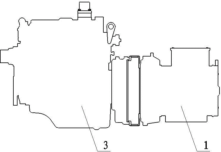
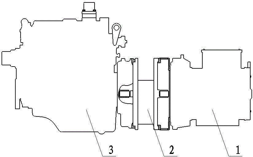
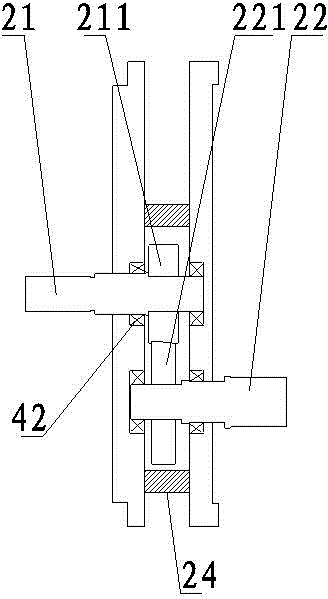
[0022] Example 1, such as figure 2 , 3 Shown, a kind of speed-adjusting generating set comprises engine 3, engine speed-regulating device and generator 1, is connected with transmission 2 between engine 3 and generator 1, and described transmission 2 is composed of casing 24, driving gear shaft 21 Constituted with driven gear shaft 22, driving gear shaft 21 is fixed with driving gear 211, driven gear shaft 22 is fixed with driven gear 221, driving gear shaft 21 is connected with engine 3 output shaft, driven gear shaft 22 is connected with generator The input shaft of machine 1 is connected, and driving gear 211 is meshed with driven gear 221, and the ratio of driving gear 211 and driven gear 221 is equal to engine optimum speed: generator optimum speed. The function of the speed changer 2 is to make both the engine and the generator work at the optimum speed, and the optimum speed of the engine 3 is used to correspond to the optimum speed of the generator 1 by gear transmis...

Embodiment 2

[0032] Example 2, such as Figure 4 As shown, transmission 2 is made of casing 24, driving gear shaft 21, driven gear shaft 22 and transition shaft 23, and driving gear shaft 21 is fixed with driving gear 211, and driven gear shaft 22 is fixed with driven gear 221, The transition shaft 23 is fixed with a first transition gear 231 and a second transition gear 232, the driving gear shaft 21 is connected with the input shaft of the engine 3, the driven gear shaft 22 is connected with the output shaft of the generator 1, and the driving gear 211 is connected with the first The transition gear 231 is meshed, and the second transition gear 232 is meshed with the driven gear 221. The rotation of the engine 3 is transmitted to the transmission 2 by the driving gear shaft 21 and then transmitted to the first transition gear 231, the second transition gear 232, and the driven gear. 221 is finally passed to Generator 1. There is a fixed block 4 between the driving gear shaft 21 and the ...


PUM


Abstract

The invention belongs to generator units and particularly discloses a speed governing generator unit. According to the technical scheme, the speed governing generator unit comprises a generator, an engine speeder and an engine and is characterized in that the generator is connected with the engine through a transmission. According to the arrangement, the engine runs at the optimal rotation speed, thereby being long in service life; the engine smaller is employed under the same power, so that the product is smaller in size and lower in cost; less oil is required, and noise is lower; due to less exhausted air quantity, the energy conservation and environment protection function is imparted to the speed governing generator unit as compared with the conventional generator unit.

Description

technical field [0001] The invention relates to a generating set, in particular to a speed-adjusting generating set. Background technique [0002] According to the relationship between generator frequency, rotational speed and magnetic pole logarithm: f=pn / 60 where P is the magnetic pole logarithm, n is the rotational speed per minute, and f is the frequency. When the machine is n=1500r / min, the generating frequency of the generator is: f=pn / 60=2x1500 / 60=50(Hz), the speed of the motor is proportional to the output frequency, since P is a fixed value, usually an integer of 2 times, and the design frequency of electrical equipment is a constant value, so the generator speed should also be kept at a constant value. At present, there are two types of generator frequencies, 50 Hz and 60 Hz, which means that the generator speed is the best Stable at 1500r / min or 1800r / min. For a synchronous generator driven by an engine, such as figure 1 As shown, the input shaft of generator 1...

Claims


Application Information

Patent Timeline
Patent Type & Authority Applications(China)
IPC IPC(8): H02K7/18H02K7/116
CPCH02K7/1807H02K7/116
Inventor 吴能建
Owner 吴迪
Features
  • R&D
  • Intellectual Property
  • Life Sciences
  • Materials
  • Tech Scout
  • Unparalleled Data Quality
  • Higher Quality Content
  • 60% Fewer Hallucinations
Learn More