Check patentability & draft patents in minutes with Patsnap Eureka AI!

a stop device

A technology for stopping devices and stopping parts, which is applied in the direction of brake parts, gear transmission mechanisms, brake types, etc., and can solve the problems of non-stop state and feed state, complex structure, insufficient clamping force, etc.

Active Publication Date: 2016-03-02
FENGH MEDICAL CO LTD
View PDF6 Cites 0 Cited by
  • Summary
  • Abstract
  • Description
  • Claims
  • Application Information

AI Technical Summary

Problems solved by technology

These stop devices in the prior art have the following disadvantages: the clamping force is insufficient; they cannot be switched between the stop state and the feed state; the structure is relatively complicated

Method used


Image

  • a stop device
  • a stop device
  • a stop device

Examples


Embodiment Construction

[0019] The present invention will be further described below in conjunction with accompanying drawing.

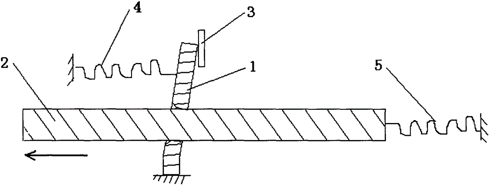
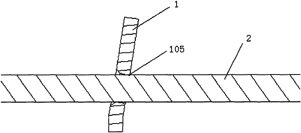
[0020] Such as figure 1 As shown, a stopping device includes a stopper 1 , a mandrel 2 , a first spring 4 and a second spring 5 . Such as figure 2 As shown, the stopper 1 includes: a first end 101 , a second end 102 and a middle portion 103 , the middle portion 103 is located between the first end 101 and the second end 102 . It should be noted that the shapes of the first end 101, the second end 102 and the middle part 103 are not affected by figure 2 The constraints shown, namely figure 2 The shapes of the first end 101 , the second end 102 and the middle portion 103 are only examples, and other shapes may be used in actual applications. In one embodiment, the stopper 1 is integrally formed as a whole. In this case, for the convenience of description, the stopper 1 is artificially decomposed into three parts: the first end 101, the second end 102 and the middle par...


PUM


Abstract

The invention relates to a stopping device which comprises a stopping part and a mandrel. The stopping part is sleeved with the mandrel and comprises a first through hole; one part of the through hole is in contact with the peripheral surface of the mandrel so as to stop the mandrel. Clamping force of the stopping device can meet the use requirement, and the stopping device can be shifted between the stopping state and the feeding state for multiple times. The stopping device is simple in structure and low in cost.

Description

technical field [0001] The invention relates to a stopping device. Background technique [0002] In the prior art, there are various stop devices, for example, some stop devices use grooves and protrusions to cooperate with each other, and some stop devices use a clamping method. These stop devices in the prior art have the following disadvantages: insufficient clamping force; incapable of multiple switching between the stop state and the feed state; and relatively complicated structure. Contents of the invention [0003] In order to overcome the above-mentioned defects in the prior art, the present invention provides a stopping device, in particular, relates to a stopping device comprising a mandrel and a stopping member. The clamping force of the stop device in the present invention can meet the requirements of use, can be switched between the stop state and the feed state for many times, has simple structure and low cost. [0004] The present invention is realized thr...

Claims


Application Information

Patent Timeline
Patent Type & Authority Patents(China)
IPC IPC(8): F16D63/00F16D65/02F16D65/22F16D121/14F16D125/18
Inventor 李风李志玉孙宝峰
Owner FENGH MEDICAL CO LTD
Features
  • R&D
  • Intellectual Property
  • Life Sciences
  • Materials
  • Tech Scout
  • Unparalleled Data Quality
  • Higher Quality Content
  • 60% Fewer Hallucinations
Learn More