Electrical box spot welding device

A technology of spot welding device and electrical box, applied in auxiliary devices, welding equipment, auxiliary welding equipment, etc., can solve the problems of low production efficiency and easy spot deviation, and achieve the effects of improving production efficiency, improving quality and accurate positioning

Inactive Publication Date: 2015-07-22
合肥凯蒙新材料有限公司
View PDF5 Cites 14 Cited by
  • Summary
  • Abstract
  • Description
  • Claims
  • Application Information

AI Technical Summary

Problems solved by technology

[0002] During the spot welding assembly of the air conditioner electrical box, the electrical box assembly has no effective positioning when spot welding its three hanging parts (elect

Method used


Image

  • Electrical box spot welding device

Examples


Example Embodiment

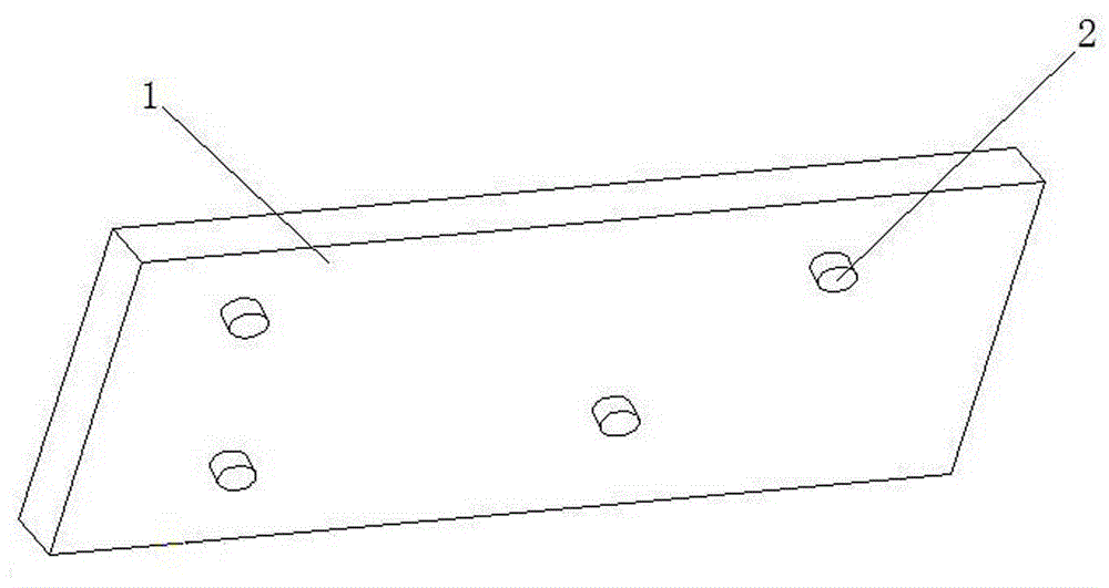
[0007] see figure 1 , this specific embodiment adopts the following technical scheme: it includes a frame body 1, and a plurality of positioning convex hulls 2 are arranged on the frame body 1, the direction of the convex hull 2 ​​is perpendicular to the paper surface inward, and the radius of the convex hull 2 ​​is is 2.75mm. By increasing the positioning convex hull, the matching mode between parts is changed from no positioning to the positioning of the convex hull and the hole. The size of the radius of the convex hull can play a positioning role without hindering the welding function of the components, and the positioning is accurate. , the production efficiency has been significantly improved, and the quality has been improved.


PUM

PropertyMeasurementUnit
Radiusaaaaaaaaaa

Abstract

The invention discloses an electrical box spot welding device and relates to the technical field of air-conditioning production. The electrical box spot welding device comprises a rack body, wherein multiple positioning protrusions are arranged on the rack body; and the direction of each protrusion is vertical to the paper surface inwards. According to the increased positioning protrusions, the matching mode of the parts is changed from a positioning-free manner to a protrusion-hole positioning manner, accurate positioning is realized after change, the production efficiency is obviously improved, and the quality is improved.

Description

Technical field: [0001] The invention relates to the technical field of air conditioner production, in particular to a spot welding device for an electrical box. Background technique: [0002] During the spot welding assembly of the air conditioner electrical box, the electrical box assembly has no effective positioning when spot welding its three hanging parts (electrical box 1, electrical box 2, electrical box 3), and employees need to rely on manual marking to ensure that all key Small size, low production efficiency and easy to point deviation. Invention content: [0003] The purpose of the present invention is to provide a spot welding device for electrical box which can accurately position welding components. [0004] In order to solve the problems existing in the background technology, the present invention adopts the following technical solution: it includes a frame body, and the frame body is provided with several positioning convex hulls, and the direction o...

Claims


Application Information

Patent Timeline
IPC IPC(8): B23K37/04
CPCB23K37/0443B23K37/04B23K2101/36
Inventor 不公告发明人
Owner 合肥凯蒙新材料有限公司
Why Eureka
Try Eureka