
Laminated punched sheet metal electronic enclosure/shield with integrated gaskets

A technology of shielding and lamination, which is applied in the direction of metal casings, electrical equipment casings/cabinets/drawers, electrical components, etc., and can solve problems such as increased production costs and large costs

Inactive Publication Date: 2015-08-12
TEKTRONIX INC
View PDF5 Cites 0 Cited by
  • Summary
  • Abstract
  • Description
  • Claims
  • Application Information

AI Technical Summary

Problems solved by technology

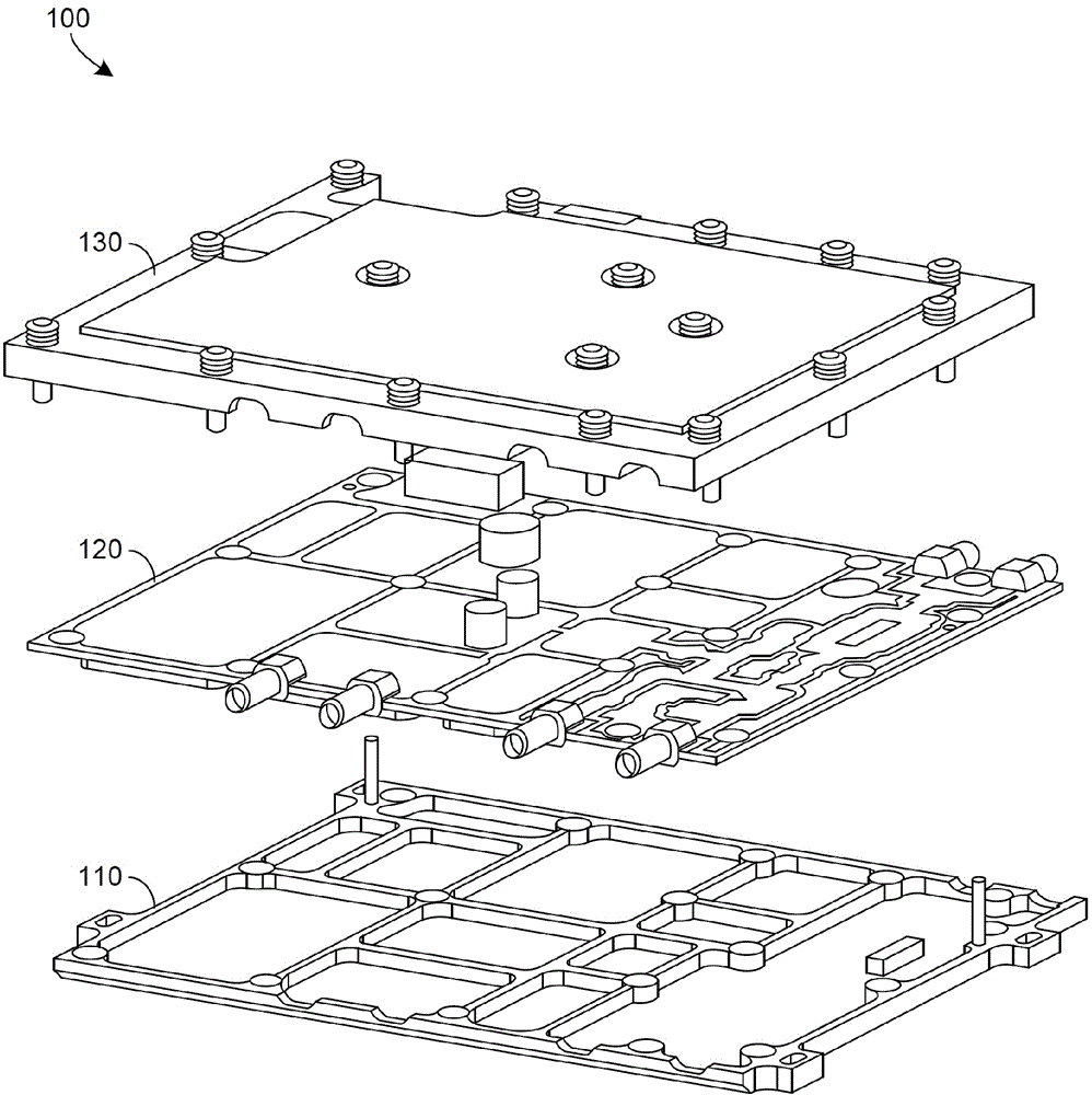
[0005] Assemblies that include one or more machined shields (e.g. figure 1 The main disadvantage of the assembly 100 shown) is the significant cost required to machine away so much material in order to create not only the inner cavity and outer surface of the machined shroud, but also the liner stop
The required machining time directly leads to significantly increased production costs

Method used


Image

  • Laminated punched sheet metal electronic enclosure/shield with integrated gaskets
  • Laminated punched sheet metal electronic enclosure/shield with integrated gaskets
  • Laminated punched sheet metal electronic enclosure/shield with integrated gaskets

Examples


Embodiment Construction

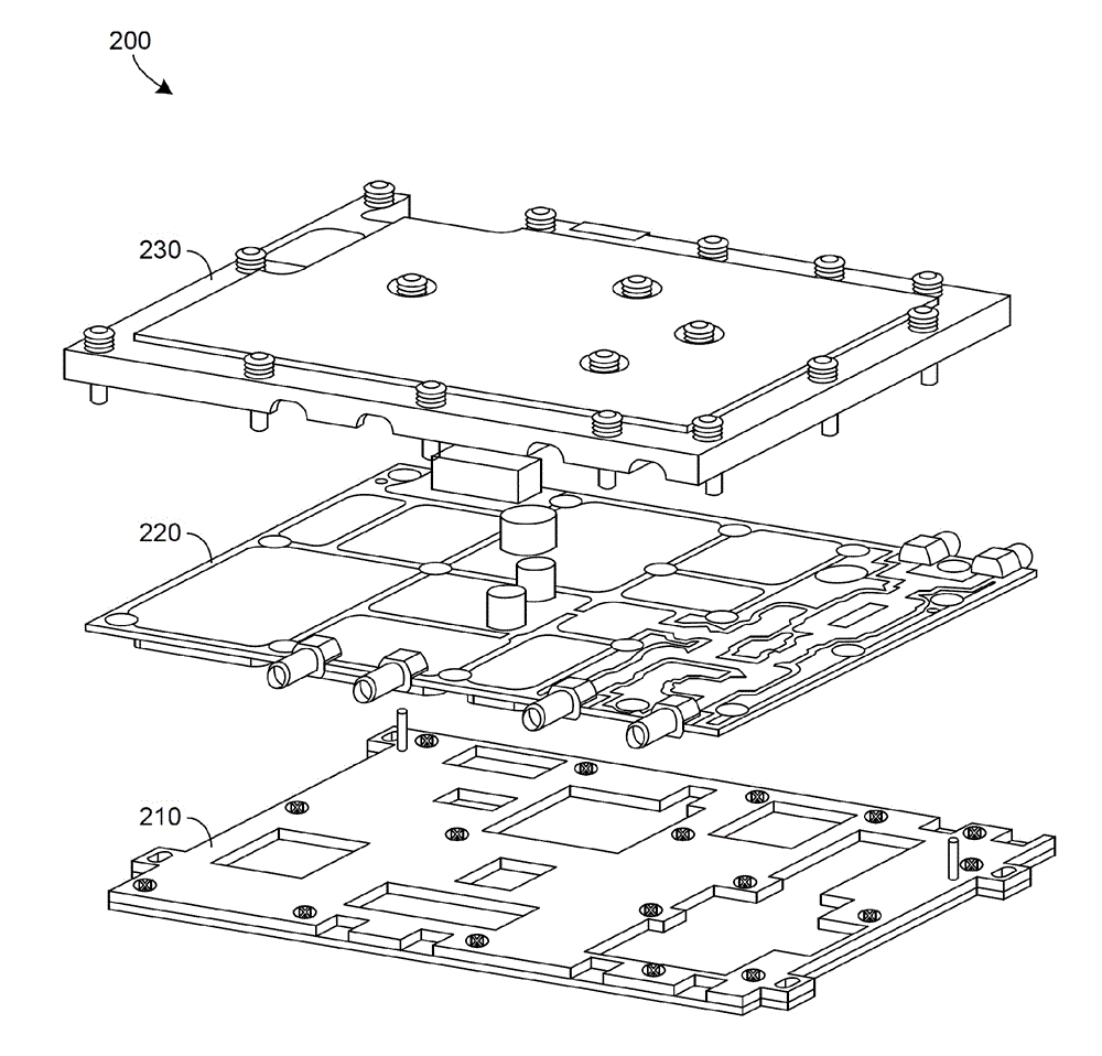
[0011] figure 2 An example of an assembly 200 suitable for housing electronic components in accordance with certain embodiments of the disclosed technology is illustrated. In an example, assembly 200 includes a printed circuit board (PCB) 220 positioned and secured between a top shield 230 and a laminated bottom shield 210 . Top shroud 230 may be machined or laminated.

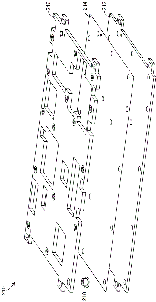
[0012] image 3 Illustrative of certain embodiments in accordance with the disclosed technology figure 2 A more detailed example of the stacked bottom shroud 210 is shown. In an example, the bottom shield 210 includes a conductive outer cover 212 that may be attached, for example, with a suitably constructed laminate material 214 such that the conductive outer cover 212 mates with the conductive punched wall section 216 . Mechanical hardware 218 may be sized to provide suitable spacing between conductive punched wall section 216 and PCB 220 such that the selected gasket material is not overly compressed....


PUM


Abstract

An assembly suitable for housing electronic components can include a top shield and a bottom shield, the bottom shield having a conductive outer cover, a wall section, and a laminating portion between the conductive outer cover and the wall section. The laminating portion may include laminating material. A printed circuit board (PCB) may be positioned between the top shield and the bottom shield.

Description

[0001] Cross References to Related Applications [0002] This application claims the benefit of U.S. Provisional Patent Application No. 61 / 936,585, entitled "LAMINATED PUNCHED SHEET METAL ELECTRONIC ENCLOSURE / SHIELD WITH INTEGRATED GASKETS," filed February 6, 2014, the contents of which are hereby incorporated by reference in their entirety . technical field [0003] The disclosed technology relates generally to housings or shrouds for housing electronic components, and more particularly to such housings or shrouds that include integrated gaskets. Background technique [0004] figure 1 An example of a currently available assembly 100 suitable for housing an electronic device is illustrated. The assembly 100 includes a machined bottom shroud 110 and a machined top shroud 130, either or both of which have form-in-place or other padding. Assembly 100 also includes a printed circuit board (PCB) 120 positioned and secured between machined bottom shield 110 and machined top shi...

Claims


Application Information

Patent Timeline
IPC IPC(8): H05K5/04
CPCH05K5/04H05K5/0217H05K9/0033H05K9/0037
Inventor M.D.斯瓦福德M.K.达斯瓦S.U.雷霍德
Owner TEKTRONIX INC
Learn More