Check patentability & draft patents in minutes with Patsnap Eureka AI!

Rotating camera relative position detection method and system

A technology of rotating camera and relative position, which is applied in signal transmission system, non-electrical signal transmission system, image communication, etc. It can solve the problems of cost increase and achieve the effect of fast identification, low cost and easy implementation

Active Publication Date: 2017-06-23
GUANGDONG OPPO MOBILE TELECOMM CORP LTD
View PDF13 Cites 0 Cited by
  • Summary
  • Abstract
  • Description
  • Claims
  • Application Information

AI Technical Summary

Problems solved by technology

But if the phone has dual cameras on the front and back, the cost will be greatly increased, because the phone needs to be equipped with 4 independent cameras

Method used


Image

  • Rotating camera relative position detection method and system
  • Rotating camera relative position detection method and system
  • Rotating camera relative position detection method and system

Examples


Embodiment 1

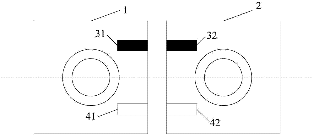
[0016] Such as figure 1 As shown, the first rotating camera 1 and the second rotating camera 2 are set on the mobile phone, and can rotate according to the axis shown by the dotted line. In the initial state, the lenses of the first rotating camera 1 and the second rotating camera 2 have the same orientation. The "same side" and "different side" referred to in Example 1 are distinguished by the orientation of the lens, that is, when the lenses of the first rotating camera 1 and the second rotating camera 2 have the same orientation, they are on the same side; When the lenses of the first rotating camera 1 and the second rotating camera 2 face opposite directions, they are in opposite states. This embodiment one provides a relative position detection system for rotating cameras, including an infrared emitting device and an infrared receiving device arranged at corresponding positions of the first rotating camera 1 and the second rotating camera 2, and also includes a controller...

Embodiment 2

[0023] Such as figure 2 As shown, the first rotating camera 1 and the second rotating camera 2 are set on the mobile phone and can rotate according to the axes shown by the dashed lines. In the initial state, the lenses of the first rotating camera 1 and the second rotating camera 2 face the same direction. The "same side" and "different side" referred to in the second embodiment are also distinguished by the orientation of the lens, that is, when the lenses of the first rotating camera 1 and the second rotating camera 2 are facing the same direction, they are on the same side; When the lenses of the first rotating camera 1 and the second rotating camera 2 face opposite directions, they are in opposite states. The second embodiment provides a relative position detection system for rotating cameras, including an infrared emitting device and an infrared receiving device arranged at corresponding positions of the first rotating camera 1 and the second rotating camera 2, and also...


PUM


Abstract

The invention relates to a detection method and system of a relative position of a rotary camera. The system comprises an infrared transmitting device and an infrared receiving device, and a controller. The infrared transmitting device and the infrared receiving device are arranged at corresponding positions of a first rotary camera and a second rotary camera. The infrared transmitting device is used for transmitting an infrared ray; and the infrared receiving device is used for receiving the infrared ray transmitted by the infrared transmitting device. The controller connected with the infrared receiving device is used for detecting the intensity of the infrared ray received by the infrared receiving device and determining relative position information of the first rotary camera and the second rotary camera according to the intensity. According to the invention, the cost is low; and the method and system can be realized easily. No interference is caused on other functional modules of the camera and the mobile terminal. And the identification accuracy is high. The method and system can be widely applied to terminal equipment that has or can be equipped with rotary cameras and includes a mobile phone and a tablet personal computer and the like.

Description

technical field [0001] The present invention relates to the technical field of rotating cameras in mobile terminal equipment, in particular to a method and system for detecting relative positions of rotating cameras. Background technique [0002] With the development of science and technology, mobile terminals such as mobile phones have increasingly powerful functions. At present, the technology of using dual cameras to take pictures has appeared on mobile terminals such as mobile phones. The dual cameras can not only obtain clearer picture quality, but also realize 3D photography, and more new functions are also being explored. But if the phone has dual cameras on the front and back, the cost will be greatly increased, because the phone needs to be equipped with four independent cameras. Based on the current rotating camera technology, two rotating cameras can be used to achieve the effect that the front and rear cameras of the mobile phone are dual cameras, and the pixels...

Claims


Application Information

Patent Timeline
Patent Type & Authority Patents(China)
IPC IPC(8): H04N17/00G08C23/04
Inventor 曾元清
Owner GUANGDONG OPPO MOBILE TELECOMM CORP LTD
Features
  • R&D
  • Intellectual Property
  • Life Sciences
  • Materials
  • Tech Scout
  • Unparalleled Data Quality
  • Higher Quality Content
  • 60% Fewer Hallucinations
Learn More