Servo-actuated support head having magneto-rheological damping function

A technology of magnetorheological damping and support head, which is used in supports, manufacturing tools, vibration suppression adjustment and other directions to achieve the effect of suppressing flutter

Inactive Publication Date: 2015-09-23
TIANJIN UNIV
View PDF7 Cites 10 Cited by
  • Summary
  • Abstract
  • Description
  • Claims
  • Application Information

AI Technical Summary

Problems solved by technology

This technical solution is passive support with simple control and is only suitable for occasions with low requirements

Method used


Image

  • Servo-actuated support head having magneto-rheological damping function
  • Servo-actuated support head having magneto-rheological damping function
  • Servo-actuated support head having magneto-rheological damping function

Examples


Embodiment Construction

[0011] The present invention will be further described in detail with reference to the accompanying drawings and embodiments. The specific embodiments described here are only used to explain the present invention, and are not used to limit the protection scope of the present invention.

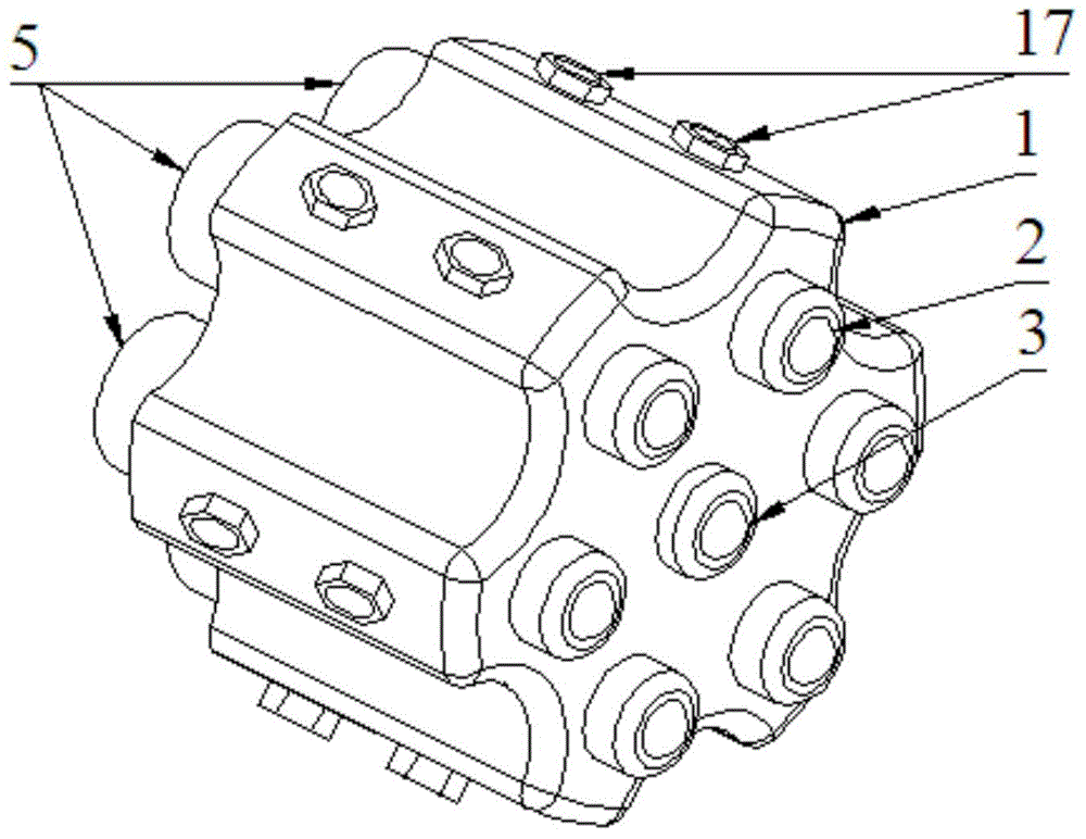
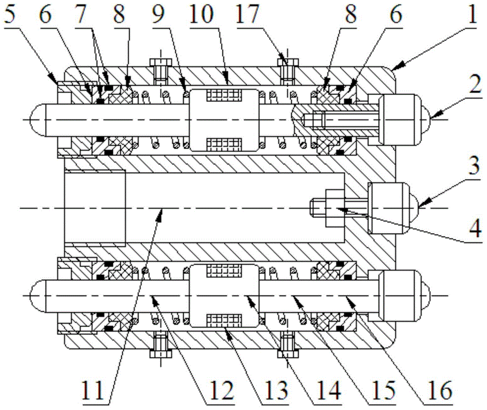
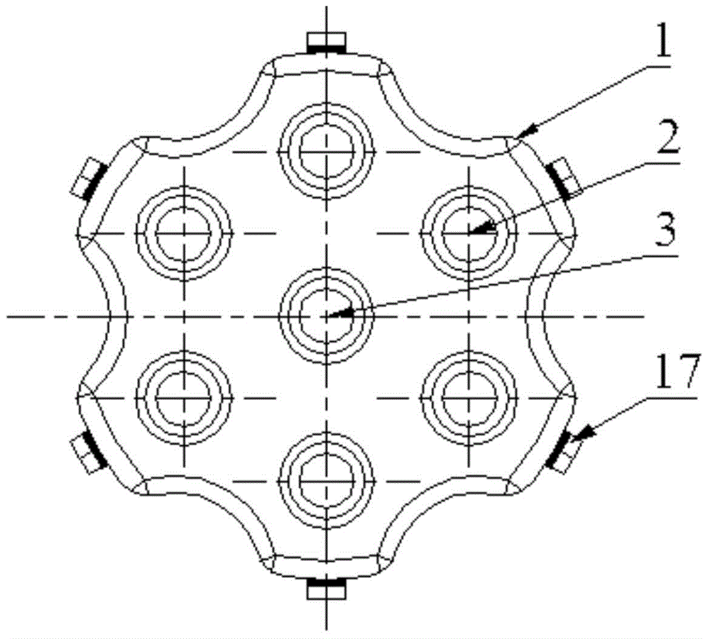
[0012] As shown in the accompanying drawings, the follow-up support head with magnetorheological damping function of the present invention includes a base 1, and a central stepped through hole 11 is opened at the middle position of the base, and the central stepped through hole 11 is opened in the middle of the base. Around the hole 11, there are a plurality of circumferential stepped through holes 10 whose axes are parallel to the axis of the central stepped through hole 11 along the same circumferential direction. There is an internal thread, and a magneto-rheological damper 16 is installed in each circumferential stepped through hole, and the magneto-rheological damper 16 includes a piston ...


PUM


Abstract

The present invention discloses a servo-actuated support head having a magneto-rheological damping function. The servo-actuated support head comprises a pedestal; the intermediate position of the pedestal is provided with a central step through hole; the periphery of the central step through hole is provided with a plurality of circumferential step through holes; the left sides of the circumferential step through holes and the central step through hole are respectively provided with an internal thread; magneto rheological dampers are respectively assembled in the circumferential step through holes; each magneto rheological damper comprises a piston; a gap is disposed between each piston and the corresponding circumferential step through hole; each piston is provided with a groove; an excitation coil is wound in each groove; two ends of each piston are respectively connected with a left piston rod and a right piston rod; each piston rod is successively sleeved with springs, a magnet resistant ring and a sealing body in a direction from inside to outside of the corresponding circumferential step through hole; the right end of each right piston rod is connected with an auxiliary universal ball; a hexagon socket headless screw sleeves the left end of each left piston rod and is connected with the internal thread at the left side of the corresponding circumferential step through hole; and a main universal ball is fixedly connected to the right end of the central step through hole via a nut. By adoption of the support head, thin-wall part flutter can be effectively suppressed.

Description

technical field [0001] The invention relates to a mirror image processing device for thin-walled parts, which is mainly used for variable damping follow-up support for thin-walled parts with weak rigidity during the mirror image processing process. Background technique [0002] Due to the characteristics of high efficiency, economy and environmental protection of mirror image processing, this processing method has been more and more applied to the processing of thin-walled parts. The mirror processing system has a processing mechanism and a supporting mechanism that are symmetrically arranged on both sides of the thin-walled part and move synchronously. Due to the weak rigidity of thin-walled parts, deformation and chatter will occur during processing. The support mechanism is to suppress chatter, improve rigidity, and improve machining accuracy. [0003] At present, the support device for mirror image processing often adopts single-point rigid support. US Patent Document ...

Claims


Application Information

Patent Timeline
Patent Type & Authority Applications(China)
IPC IPC(8): B23Q3/00F16F9/53
CPCB23Q3/00B23Q2703/10F16F9/53F16F9/535
Inventor 肖聚亮姚永胜黄田林彬楫骏林滨张晓峰
Owner TIANJIN UNIV
Why Eureka
Try Eureka