Overload relief valve

A technology of unloading valve and valve body, applied in the field of hydraulic system, can solve the problems of large oil pressure difference, complicated connection and installation, complicated installation, etc., and achieve the effect of reducing cost, using less quantity, and simplifying the installation process.

Inactive Publication Date: 2015-10-21
宁波诚威液压科技有限公司
View PDF9 Cites 3 Cited by
  • Summary
  • Abstract
  • Description
  • Claims
  • Application Information

AI Technical Summary

Problems solved by technology

[0003] Although the single oil pump oil circuit of the prior art hydraulic system has the function of unloading oil pressure, it still has the following three defects: 1, because an electric control device is provided, it must be connected to an external power supply to work normally; 2, There are too many components that need to be used, which not only increases the cost, but also complicates the installation between the components. In addition, the manufacture

Method used


Image

  • Overload relief valve

Examples


Example Embodiment

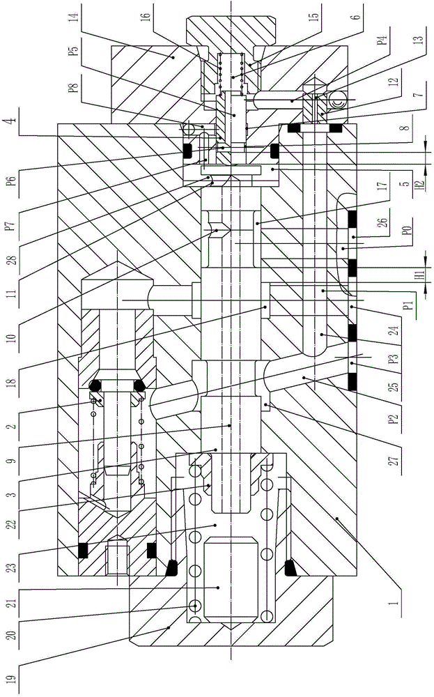
[0019] The overload relief valve of the present invention will be further described below in conjunction with the accompanying drawings and specific embodiments:

[0020] like figure 1 As shown, the overload relief valve of the present invention includes a valve body 1, a one-way valve 2, a main valve core 3, a control valve core 4, an oil inlet channel P1, an oil outlet channel P2, an oil return channel P0, a first spring adjustment A pressure mechanism, a second spring pressure regulating mechanism, a first oil passage mechanism, a second oil passage mechanism, a third oil passage mechanism, and a fourth oil passage mechanism. The check valve 2 is arranged on the upper part of the valve body 1, the oil inlet cavity of the check valve 2 is communicated with the oil inlet passage P1, and the oil outlet chamber of the check valve 2 is communicated with the oil outlet passage P2. The main valve core 3 can slide left and right in the valve body 1 , and a first sealing oil cavity...


PUM


Abstract

Provided is an overload relief valve. The overload relief valve comprises a valve body, a main valve element, a control valve element, an oil inlet channel, an oil outlet channel, an oil return channel, a one-way valve, a first spring pressure regulation mechanism and a second pressure regulation mechanism, wherein the first spring pressure regulation mechanism and the second pressure regulation mechanism are connected to the left and right ends of the valve body respectively. The left end of the main valve element is connected with the first spring pressure regulation mechanism, and a first seal oil cavity is formed between the right end face of the main valve element and the second spring pressure regulation mechanism. A second seal oil cavity is formed between the right end face of the control valve element and the second spring pressure regulation mechanism. The oil outlet channel is communicated with the second seal oil cavity through a first oil channel mechanism. A second oil channel mechanism through which the first seal oil cavity and the second seal oil cavity can be communicated is arranged on the control valve element. A third oil channel mechanism through which the oil inlet channel and the oil return channel can be communicated is arranged between the valve body and the main valve element. The diameter of the main valve element is larger than that of the control valve element, and the load relief stroke of the main valve element is larger than the pressure regulation stroke of the control valve element. The overload relief valve does not need any external power source, so that cost is low, and installation is easy and convenient; in addition, a low balanced oil pressure can be kept while a motor is protected.

Description

Technical field: [0001] The invention belongs to the technical field of hydraulic systems, in particular to an overload relief valve used for an oil circuit of a single oil pump in a hydraulic system. Background technique: [0002] In the single oil pump oil circuit of the hydraulic system in the prior art, a structure in which an oil tank, an oil pump, a relief valve, a one-way valve and a single-acting oil cylinder are connected in sequence is usually adopted. The motor drives the work, and a two-position two-way solenoid valve needs to be connected between the oil inlet of the single-acting cylinder and the fuel tank. Return to the fuel tank to restore the return stroke of the single-acting cylinder to the initial state. During the working process of the single oil pump oil circuit of this structure, the oil pump often works under excessive oil pressure due to excessive load, so that the motor is also overloaded, resulting in damage to the motor, and the relief valve con...

Claims


Application Information

Patent Timeline
IPC IPC(8): F15B13/02
CPCF15B13/025
Inventor 韩峰
Owner 宁波诚威液压科技有限公司
Why Eureka
Try Eureka