Check patentability & draft patents in minutes with Patsnap Eureka AI!

Manual Pulse Generator

A technology of manual pulse generation and angular position, which is applied in the direction of transmitting the sensing member by using an electric/magnetic device, which can solve the problems of early wear of the tooth portion, difficulty in obtaining durability, and difficulty in obtaining a sense of engagement, and achieves reliable performance. Engagement feeling, effect of suppressing tooth wear

Active Publication Date: 2018-03-30
SANKYO SEIKI MFG CO LTD
View PDF7 Cites 0 Cited by
  • Summary
  • Abstract
  • Description
  • Claims
  • Application Information

AI Technical Summary

Problems solved by technology

[0006] However, in the case of using the magnetic force between the magnets as in the structures described in Patent Documents 1 and 2, it is difficult to obtain a clear sense of engagement because the magnetic force changes continuously.
In addition, in the structure in which the ball is in contact with the engaging gear as in the structure described in Patent Document 3, since the tooth portion and the ball are in point contact, early wear of the tooth portion and a decrease in the engagement feeling during use tend to occur. question
In particular, in a manual pulse generating device, since the engaging operation is frequently performed, the engaging mechanism is required to have sufficient durability, but it is difficult to obtain sufficient durability in the structure described in Patent Document 3.

Method used


Image

  • Manual Pulse Generator
  • Manual Pulse Generator
  • Manual Pulse Generator

Examples


Embodiment Construction

[0084] A manual pulse generator to which the present invention is applied will be described with reference to the drawings.

[0085] (The overall structure of the manual pulse generator)

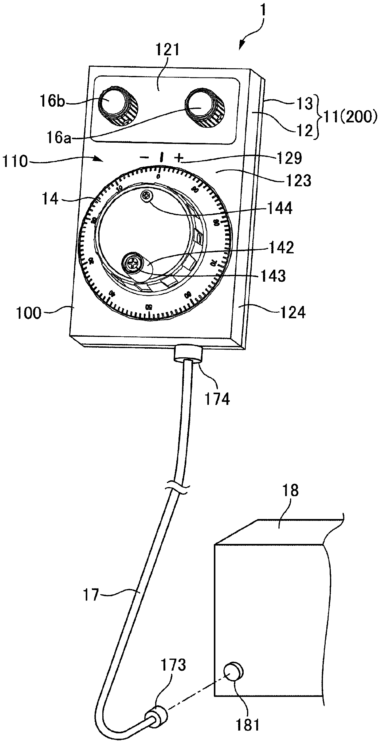
[0086] figure 1 It is an explanatory diagram showing the appearance of the manual pulse generator 1 to which the present invention is applied. figure 2 It is an exploded perspective view of the manual pulse generator 1 to which the present invention is applied. In addition, in figure 2 Among others, in the direction in which the rotation center axis L of the rotating body 6 extends (rotation center axis L direction), the operation surface side is denoted as L1, and the back side is denoted as L2.

[0087] exist figure 1 as well as figure 2 In the illustrated manual pulse generator 1 , a dial 14 that is manually rotatable is provided on the front surface of the device body 100 , and marks 129 showing reference positions and polarities are marked around the dial 14 . The dial 14 const...


PUM


Abstract

The present invention provides a manual pulse generator capable of obtaining a clear engagement feeling when rotating a rotating body and having an engagement mechanism with excellent durability. In the sensor unit (10) of the manual pulse generating device, when the rotating body (6) is rotated by manual operation, the rotation is detected by the sensor unit (8), and a pulse is generated based on the detection result. Furthermore, an engagement mechanism (7a) is provided between the rotating body (6) and the supporting body (200). The abutting part (70) engaged with the teeth (633) of the engaging gear (63) in the engaging mechanism (7a) is a shaft (71), and the shaft (71) passes through a spring member formed by a coil spring (76) ( 75) is pressed to the outer peripheral surface (630) of the engaging gear (63). The shaft (71) has a length equal to or greater than the width of the tooth (633), and abuts on the entire width of the tooth (633).

Description

technical field [0001] The invention relates to a manual pulse generating device for generating pulses through manual operation. Background technique [0002] Manual pulse generators used to set machining conditions for numerically controlled machine tools such as machining centers or to check the operation of electronic equipment, etc., generate pulses corresponding to the rotation angle of the rotating body when rotating a rotating body such as a dial by manual operation. In such a manual pulse generator, an engaging mechanism is provided to the rotating body to improve the operational feeling of the rotating body and to control the stop position of the rotating body and the like. A structure utilizing the magnetic force between magnets has been proposed as the engagement mechanism (see Patent Documents 1 and 2). In addition, a structure in which a ball is brought into contact with an engagement gear provided on a rotating body has been proposed (see Patent Document 3). ...

Claims


Application Information

Patent Timeline
Patent Type & Authority Patents(China)
IPC IPC(8): G01D5/244
Inventor 沟口敏夫小林一雄
Owner SANKYO SEIKI MFG CO LTD
Features
  • R&D
  • Intellectual Property
  • Life Sciences
  • Materials
  • Tech Scout
  • Unparalleled Data Quality
  • Higher Quality Content
  • 60% Fewer Hallucinations
Learn More