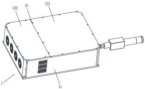
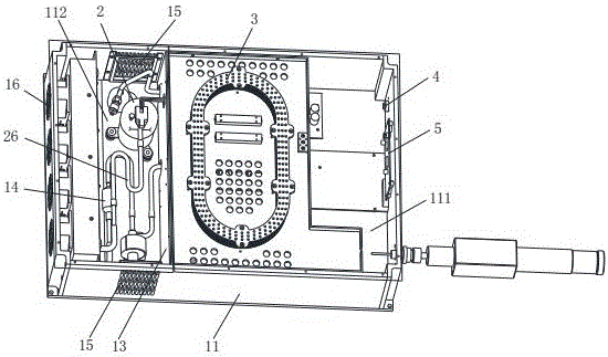
[0104] like Figure 1 to Figure 12 As shown, the fiber laser with high-efficiency temperature control device of the present invention includes a case 1 and a micro compressor direct cooling system 2 , an optical system 3 , a circuit system 4 and a control system 5 accommodated in the case 1 .
[0105] Chassis 1 is a separate laser chassis, such as figure 1 , figure 2 As shown, it includes a box 11, a box cover 12, a partition 13 and a screen filter 14; the partition 13 is assembled in the box 11, and divides the built-in space of the cabinet 1 into an optical circuit section 111 and a heat dissipation section 112; the box plate of the heat dissipation section 112 is provided with an air inlet channel 15 and an air outlet channel 16 to dissipate heat by convection with the external ambient air; the screen filter 14 is arranged on the air inlet channel 15 of the heat dissipation section 112 to isolate the air Ingress of sundries during convection;
[0106]The box body cover 12 is matched with the box body 11, and is made of the first box body cover 121 and the second box body cover 122; The optical circuit section 111 is matched; the second box cover 122 is assembled and connected with the box body and the partition plate 13 of the heat dissipation section 112 , and is matched with the heat dissipation section 112 .
[0107] like Figure 3 to Figure 10 As shown, the compressor refrigeration system 2 is installed in the box body 11, including a micro-compressor 21, a condenser 22, a throttling device 23, an evaporative cold plate 24, and a refrigerant injection port 25 respectively connected through a plurality of connecting copper pipes 26. ;
[0108] The micro-compressor 21 is fixedly mounted on the cooling section 112 of the cabinet 1, the micro-compressor is preferably a micro-inverter compressor, and the outlet port 212 is connected to the inlet port 221 of the condenser 22 through the first connecting copper pipe 261;
[0109] The condenser 22 is assembled in the air outlet duct 16 of the heat dissipation section 112 of the chassis, and is provided with a condenser fan 223; the condenser fan 223 is used to dissipate heat to the condenser 22; Connect the inlet port 231 of the throttling device 23;
[0110] The throttling device 23 is arranged between the condenser 22 and the evaporative cold plate 24, and the outlet end 232 of the throttling device 23 is connected to the inlet end 241 of the evaporative cold plate 24 through a third connection copper pipe 263;
[0111] The evaporative cold plate 24 is assembled on the optical path circuit section 111 of the cabinet 11 of the chassis 1, and the evaporative cold plate 24 is provided with a micro-shaped flow channel structure 243, and one or both sides are a flat structure; the micro-channel 243 can be set to multiple The channels are connected in parallel or in series; the outlet end 242 of the evaporative cold plate 24 is connected to the inlet end 211 of the micro compressor 21 through the fourth connecting copper pipe 264; sensor assembly holes 244 can be set on the evaporative cold plate as required;
[0112] The refrigerant filling port 25 is located between the outlet end 242 of the evaporative cold plate 24 and the inlet end 211 of the micro compressor 21, thus forming a fully closed refrigerant circulation system.
[0113] The circuit system 4 includes a circuit board 41 and a power interface 42. The power interface 42 is electrically connected to the circuit board 41 and connected to an external power input.
[0114] like image 3 , Figure 4 , Figure 9 and Figure 10 As shown, the optical system 3 at least includes a pump source 31, a grating 32, an optical fiber 33, an optical fiber disk 34 and a collimation isolator 35;
[0115] The pump source 31 is fixedly installed on the evaporative cold plate 24, and is in direct or indirect contact with the evaporative cold plate 24; the pump source 31 is provided with a sensor installation hole 311; the evaporative cold plate 24 and the pump source 31 are fixedly installed in the box The optical path circuit section 111 of 11;
[0116] The grating 32 includes a first grating 321 and a second grating 322;
[0117] The optical fiber 33 includes a gain optical fiber 331 and a transmission optical fiber 332;
[0118] The fiber optic disk 34 is a composite fiber optic disk, comprising an optical fiber microchannel 341 and an optical fiber fixing plate 342; wherein the gain fiber 331 is coiled along the fiber microchannel 341 of the fiber optic disk 34, and the fiber fixing plate 342 fixes and protects the gain fiber 331 on the fiber optic disk microchannel. On the channel 341; the first grating 321 is connected to the pump source 31 and the gain fiber 331, the second grating 322 is connected to the gain fiber 331 and the transmission fiber 332, and the first grating 321 and the second fiber 322 are fixedly installed on the fiber optic disk 34; the transmission fiber 332 is connected to the collimation isolator 35;
[0119] The collimating isolator 35 is placed outside the box 11 .
[0120] like Figure 11 , Figure 12 As shown, the control system 5 is an integrated control system, including a laser main control board 51, a communication interface 52, a cooling control board 53, a compressor driving board 54, a temperature sensor 55 and a pump source driver 56;
[0121] The laser main control board 51 is connected to the communication interface 52, the communication interface 52 receives external input commands, the laser main control board 51 is connected to the circuit board 41 to receive circuit input, the laser main control board 51 is connected to the refrigeration control board 53 and the pump source driver 56, Control the operation of the refrigeration system 2 and the optical path system 3 respectively; the pump source driver 56 is connected to the pump source 31 to control the operation of the pump source 31;
[0122] The temperature sensor 55 is installed in the temperature sensor mounting hole 311 on the pumping source 31 or in the temperature sensor mounting hole 244 on the evaporative cold plate 24, and is connected to sense the temperature of the pumping source 31;
[0123] Refrigeration control board 53 is connected with temperature sensor 55, compressor driving board 54 and condenser fan 223, and refrigeration control board 53 receives the signal input of temperature sensor 55 and controls the miniature compressor 21 of refrigeration system 2 according to the instruction of laser main control board 51 , the opening and rotating speed of the condenser fan 223;
[0124] The compressor drive board 54 is connected to the refrigeration control board 53 and the micro compressor 21, and receives the input signal from the refrigeration control board 53 to control the opening and rotating speed of the compressor 21;
[0125] The pumping source driver 56 is arranged in the box body 11 of the chassis 1, connects the laser main control board 51, the pumping source 31 and the circuit board 41, receives the circuit input of the circuit board 41, and pumps according to the instruction of the laser main control board 51. The source 31 performs current voltage control.
[0126] Among them, the pump source 31 can choose one or more pump sources according to the power of the laser; the compressor refrigeration system 2 can match one or more compressors according to the heat demand of the pump source; The requirement of the laser pumping source 31 is set to a single large-sized evaporative cold plate 24 or multiple small-sized evaporative cold plates 24 .
[0127] The specific working process of the fiber laser containing the high-efficiency temperature control device of the present invention is as follows:
[0128] The working process of the compressor direct cooling system 2: the compressor direct cooling system 2 is a fully enclosed refrigerant circulation system, the micro compressor 21 pushes the refrigerant into the condenser 22, the condenser fan 223 dissipates heat to the condenser 22, and the refrigerant after cooling passes through The throttling device 23 enters the evaporative cold plate 24, and concentrates the cooling output on the evaporative cold plate 24, and the refrigerant returns to the micro compressor 21 after the heat exchange between the evaporative cold plate 24 and the pump source 31;
[0129] The main heating source of the laser, the pump source 31, is in direct or indirect contact with the evaporative cold plate 24 for heat exchange, and the temperature sensor 55 is installed in the temperature sensor mounting hole 311 on the pump source 31 or in the temperature sensor assembly hole on the evaporative cold plate 24 244, the throttling device 23 is located at the inlet port 241 of the evaporative cold plate 24, and the refrigeration control board 53 receives the instruction of the laser main control board 51 and the signal feedback of the temperature sensor 55, and controls the opening and closing of the micro compressor 21 and the condenser fan 223. The rotating speed is matched with the heat energy generated by the pump source 31 in real time, and the cooling capacity equal to that required by the pump source 31 is output, and the working temperature of the pump source 31 is controlled within a precise range to ensure the stability of the output wavelength;
[0130] The partition 13 divides the box body 11 into a laser optical path circuit section 111 and a heat dissipation section 112; the heat dissipation section 112 and the external environment air convective heat dissipation, and the debris entering during air convection is isolated by setting a screen filter 14; the optical path circuit Components are mounted on the optical circuit section 111 .
[0131] The laser main control board 51 receives external input commands, turns on or off the optical system 4 and controls the voltage and current of the optical system. The laser main control board 51 controls the opening and rotating speed of the compressor 21 and the condenser fan 223 through the refrigeration control board 53, and the refrigeration control board 53 receives the temperature signal of the temperature sensor 55 and the command signal of the laser main control board 51, and the cooling system 2 Matching control is performed to generate cooling capacity equal to the heat dissipation requirement of the pump source 31, so as to realize precise temperature control of the pump source 31.
[0132] The fiber laser of the present invention may refer to different types of fiber lasers, such as pulsed fiber lasers, continuous fiber lasers, quasi-continuous fiber lasers and fiber laser amplifiers. For ultra-high-power giant energy fiber lasers, a single high-power compressor and multiple evaporative cold plates or multiple micro-compressor refrigeration systems and multiple evaporative cold plates can be used to directly cool and control the pump source. It is an application expansion based on the present invention.