Supercharge Your Innovation With Domain-Expert AI Agents!

Bubble blowing system for stage

A stage and console technology, applied to stage devices, devices for theaters, circuses, etc., entertainment, etc., can solve problems such as being only affected by gravity and wind, short time in the air, erratic bubbles, etc., to prevent Effects of escape, unbreakable, and rich motion effects

Active Publication Date: 2017-03-22
NANLING WANGKE INTPROP MANAGEMENT CO LTD
View PDF6 Cites 0 Cited by
  • Summary
  • Abstract
  • Description
  • Claims
  • Application Information

AI Technical Summary

Problems solved by technology

[0004] The traditional bubble machine can only make bubbles and blow them into an area through the blower. The structure is relatively simple and the functions realized are relatively simple. In order to further improve the atmosphere effect of the bubble machine, the present invention proceeds from the following aspects Structural optimization and functional upgrade
[0005] 1. The bubbles blown out by the traditional bubble machine are erratic and have a short time in the air. They cannot be limited to a fixed area. After blowing out, they are only affected by gravity and wind.
[0006] 2. When the light environment is good, the bubbles blown by the traditional bubble machine will produce colorful visual effects due to the dispersion caused by the reflection, refraction and interference of light on the film.
When the lighting environment is not good or the viewing angle is not suitable, the visual effect will be greatly reduced
[0007] 3. The bubbles blown by the traditional bubble machine are easily broken in a short time due to evaporation, touch and airflow

Method used


Image

  • Bubble blowing system for stage
  • Bubble blowing system for stage
  • Bubble blowing system for stage

Examples


Embodiment Construction

[0021] The present invention will be described in further detail below in conjunction with the accompanying drawings and specific embodiments.

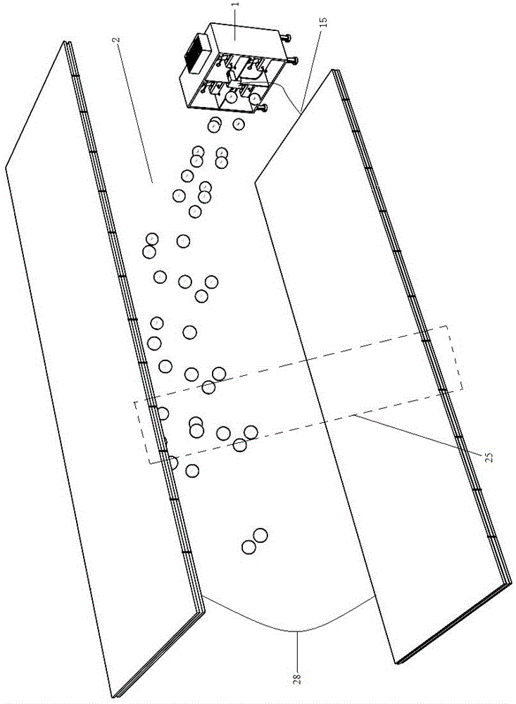
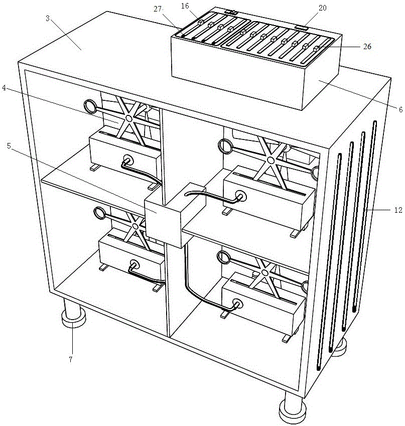
[0022] figure 1 As shown, the bubble blowing system for the stage includes a bubble blowing device 1 and an external electric field device 2; figure 2 As shown, the bubble blowing device 1 includes: a support shell 3, at least one bubble blowing unit 4, an electrostatic generator 5, and a console 6; the lower end surface of the support shell 3 is provided with insulating legs 7; the bubble blowing unit 4 is installed on the support shell within 3.

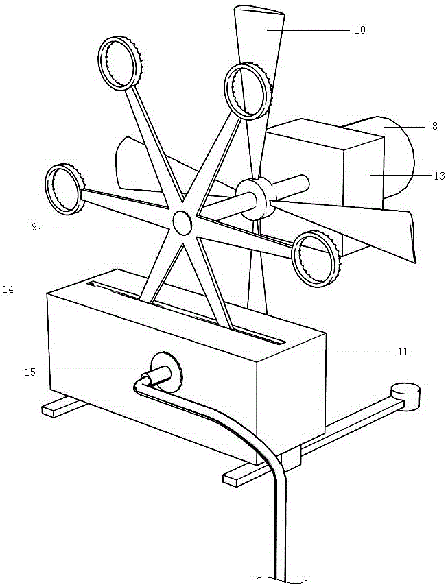
[0023] Such as image 3 As shown, the bubble blowing unit 4 includes a driving motor 8, a liquid dipping wheel 9, a fan 10, and an insulating liquid storage bin 11; the liquid dipping wheel 9 is located at the opening end of the supporting shell 3; between; the support shell 3 is provided with an air intake grid 12 that matches the position of the fan 10; The output end is connected; ...


PUM


Abstract

The invention discloses a novel bubble blowing system for a stage and relates to the technical field of stage equipment. The novel bubble blowing system comprises a bubble blowing device and an external electric field device. The bubble blowing device comprises a supporting shell, one or more bubble blowing units, a static generator and a control table. The external electric field device comprises an electrode net A, an electrode net B and a limiting electrostatic plate, wherein the electrode net A is located on the upper portion of the external electric field device and arranged in parallel, the electrode net B is located on the lower portion of the external electric field device and arranged in parallel, and the limiting electrostatic plate surrounds the electrode net B in the horizontal direction. The electrode net A and the electrode net B form a plane-parallel capacitor. An electric quantity general control adjusting button is arranged at the position, on the control table, of the plane-parallel capacitor. The limiting electrostatic plate is connected with a discharging probe of the static generator. The electrode net A is clamped between two layers of soft insulation skin A, and the electrode net B and the limiting electrostatic plate are clamped between soft insulation skin B. According to the novel bubble blowing system, bubbles with elastic electricity brown out by the novel bubble blowing system can be limited between the plane-parallel capacitor, self-illumination is achieved through fluorescent agents under the condition that light rays are weak, and the stage effect is greatly enriched.

Description

technical field [0001] The invention relates to the technical field of stage equipment, in particular to a bubble blowing device. Background technique [0002] At present, with the improvement of people's aesthetic standards, the level of visual effects created by the sound and light of the stage is also getting higher and higher. The continuous improvement of stage equipment technology has made the atmosphere effect that was difficult to achieve in the past continue to become a reality. [0003] The bubble machine for the stage is composed of a circuit system, a blower system, and a bubble making device. To put it simply, after the electricity is turned on, the motor drives the fan blades inside to rotate, and at the same time the ring that makes the bubbles also rotates. The ring will pass through the liquid that makes the bubbles, the liquid will be stained on it, and the blower behind it will blow air, so a large number of bubbles will appear continuously. [0004] The...

Claims


Application Information

Patent Timeline
Patent Type & Authority Patents(China)
IPC IPC(8): A63J5/02A63H33/28
Inventor 俞江廉佳李发兵
Owner NANLING WANGKE INTPROP MANAGEMENT CO LTD
Features
  • R&D
  • Intellectual Property
  • Life Sciences
  • Materials
  • Tech Scout
  • Unparalleled Data Quality
  • Higher Quality Content
  • 60% Fewer Hallucinations
Learn More