Flue gas desulfurization and denitrification system

A technology for desulfurization and denitrification and flue gas, which is applied in the field of flue gas desulfurization and denitrification systems, can solve problems such as low denitrification efficiency, system scaling, and harm to human health, so as to facilitate equipment operation and maintenance, avoid scaling problems, and reduce equipment The effect of investment

Inactive Publication Date: 2015-12-16
NANJING BAIYUN CHEM ENVIRONMENTAL MONITORING
View PDF7 Cites 6 Cited by
  • Summary
  • Abstract
  • Description
  • Claims
  • Application Information

AI Technical Summary

Problems solved by technology

[0002] At present, the flue gas of existing industrial boilers will produce sulfur and nitrogen oxides, which are the main substances of air pollution, seriously destroying the ecological environment and endangering human health.
[0003] The existing flue gas denitrification methods mainly include: flue gas denitrification selective catalytic reduction method (abbreviated as SCR), selective non-catalytic reduction method (abbreviated as SNCR), low-nitrogen combustion, etc., among which SNCR and low-nitrogen combustion denitration efficiency High, it is impossible to achieve deep removal of nitrogen oxides. Although SCR has the advantages of mature and reliable process and high denitrification efficiency, it can stably control nitrogen oxides at 70mg/Nm3 in the early stage of catalyst operation under the condition that ammonia escape does not exceed the standard. , even close to 60mg/Nm3
However, to achieve the goal of less than 50mg/Nm3, it is necessary to increase the amount of catalyst and reducing agent used, and the increase in the amount of catalyst used will increase the concentration of SO3 at the flue gas outlet, and the increase in the amount of reducing agent injected will cause ammonia gas to escape. Both will lead to clogging of the air preheater; on the other hand, it will also increase the cost and energy consumption of denitrification
[0004] The main methods of flue gas denitrification are: acid method, alkali method, limest

Method used


Image

  • Flue gas desulfurization and denitrification system

Examples


Example Embodiment

[0016] In order to deepen the understanding of the present invention, the present invention will be described in further detail below in conjunction with embodiments and drawings. The embodiments are only used to explain the present invention and do not constitute a limitation on the protection scope of the present invention.

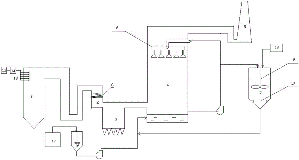
[0017] See figure 1 As shown, a flue gas desulfurization and denitrification system includes a coal-fired boiler 1, an SCR reactor 2, a dust collector 3, an absorption tower 4, and a chimney 5 connected in sequence through a flue gas pipeline. The furnace of the coal-fired boiler 1 is connected to denitrification Reductant injection module, the SCR reactor 2 is provided with a denitration catalyst layer 6; the lower part of the absorption tower is provided with an lye inlet and a lye outlet, and the lye outlet is respectively fed to the regeneration reactor 7 The outlet and the spray system 8 on the top are connected. The outlet of the regenerative reactor...


PUM


Abstract

The invention discloses a flue gas desulfurization and denitrification system. The system comprises a coal-fired boiler, an SCR (selective catalytic reduction) reactor, a dust remover, an absorption tower and a chimney which are sequentially connected through a flue gas pipeline, wherein a combustion chamber of the coal-fired boiler is connected with a denitrification reducing agent jet module, and a denitrification catalyst layer is arranged in the SCR reactor; an alkali liquor inlet and an alkali liquor outlet are arranged at the lower part of the bottom of the absorption tower, the alkali liquor outlet is communicated with a feeding port of a lime water reactor and a spray system at the top of the feeding port respectively, a discharging port of the lime water reactor is connected with the alkali liquor inlet, the system further comprises a slaked lime charging mechanism connected with the feeding port of the lime water reactor and a caustic soda supply device connected with the alkali liquor inlet, the upper part of the lime water reactor is cylindrical, the diameter of the lower part decreases gradually, a stirring paddle is arranged in the upper part of the lime water reactor, and a filter net is detachably arranged at the lower part. The equipment is low in one-time investment and energy consumption, and the desulfurization and denitrification efficiency is higher than 95%.

Description

technical field [0001] The invention belongs to the field of environmental protection, in particular to a flue gas desulfurization and denitrification system. Background technique [0002] At present, the flue gas of existing industrial boilers will produce sulfur and nitrogen oxides, which are the main substances of air pollution, seriously destroying the ecological environment and endangering human health. [0003] The existing flue gas denitrification methods mainly include: flue gas denitrification selective catalytic reduction method (abbreviated as SCR), selective non-catalytic reduction method (abbreviated as SNCR), low-nitrogen combustion, etc., among which SNCR and low-nitrogen combustion denitration efficiency High, it is impossible to achieve deep removal of nitrogen oxides. Although SCR has the advantages of mature and reliable process and high denitrification efficiency, it can stably control nitrogen oxides at 70mg / Nm3 in the early stage of catalyst operation u...

Claims


Application Information

Patent Timeline
IPC IPC(8): B01D53/75B01D53/90B01D53/78B01D53/96B01D53/50B01D53/56F23J15/02
Inventor 胡家富冯建琳党元军王芸刘婷婷
Owner NANJING BAIYUN CHEM ENVIRONMENTAL MONITORING
Why Eureka
Try Eureka