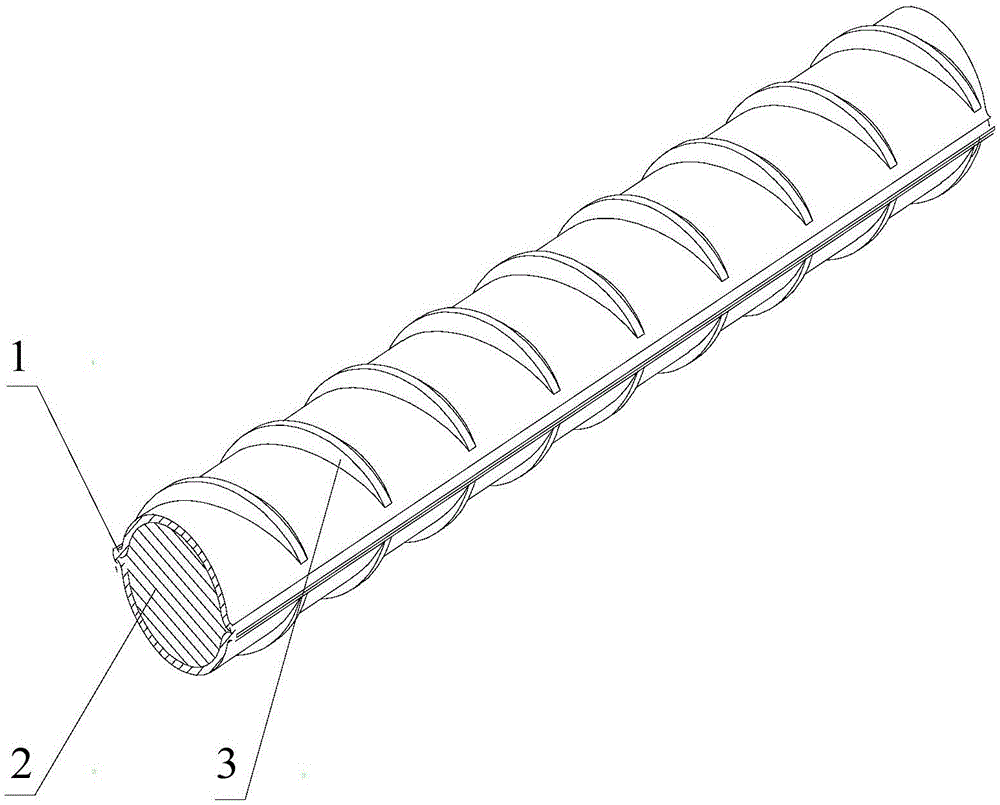
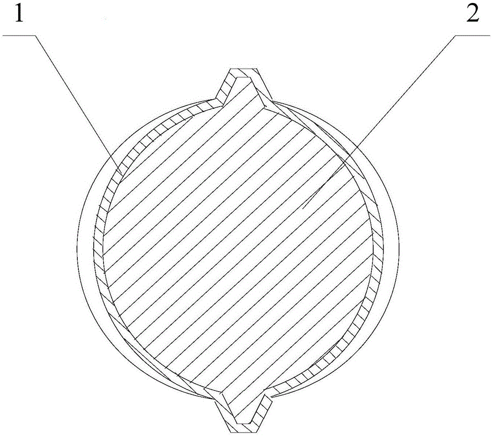
Stainless steel/carbon steel bi-metal thread steel and composite molding technology thereof
A composite molding, stainless steel technology, applied in the direction of metal layered products, lamination, building elements, etc., to achieve the effect of reducing engineering costs, improving strength, and saving stainless steel materials
- Summary
- Abstract
- Description
- Claims
- Application Information
AI Technical Summary
Problems solved by technology
Method used
Image

Examples
Embodiment 1
[0072] In this embodiment, 304 stainless steel and HRB335 steel billets are used, and finally rolled into bimetallic rebar with a diameter of Φ25mm.
[0073] Such as Figure 4 and Figure 5 As shown, it is a schematic diagram of the basic structure of a bimetal blank provided by the embodiment of the present invention.
[0074] In this embodiment, the stainless steel pipe blank 4 of the outer layer is made of 304 stainless steel, and the stainless steel steel pipe blank 4 is a round seamless steel pipe, and its specific size is Φ150×5×2000 (outer diameter×wall thickness×length, mm). The carbon steel core blank 5 of the core adopts the blank used for producing HRB400 rebar, and its specific size is Φ140.07×2000 (outer diameter×length, mm), the carbon steel core blank 5 and the stainless steel pipe blank 4 The interference between them is 0.07mm.
[0075] The stainless steel pipe blank 4 is firstly deburred on the inner surface, then pickled, and finally cleaned with acetone....
Embodiment 2
[0081] In this embodiment, 316L stainless steel and the blank for producing HRB500 rebar will be used, and finally rolled into bimetallic rebar with a diameter of Φ28mm.
[0082] Such as Figure 6 As shown, it is a schematic diagram of the basic structure of another bimetal blank provided by the embodiment of the present invention.
[0083]In this embodiment, the outer stainless steel pipe blank 4 is made of 316L stainless steel, and the stainless steel steel pipe blank 4 is an equilateral rectangular seamless steel pipe, and its specific size is 160×5×3000 (side length×wall thickness×length, mm). The carbon steel core blank 5 of the core adopts the blank used for producing HRB500 rebar, and its concrete size is 150.5 * 3000 (side length * length, mm), the distance between the carbon steel core blank 5 and the stainless steel pipe blank 4 The amount of interference is 0.5mm.
[0084] The stainless steel pipe blank 4 is firstly deburred on the inner surface, then pickled, and...
PUM
| Property | Measurement | Unit |
|---|---|---|
| Diameter | aaaaa | aaaaa |
| Diameter | aaaaa | aaaaa |
Abstract
Description
Claims
Application Information
 - Generate Ideas
- Intellectual Property
- Life Sciences
- Materials
- Tech Scout
- Unparalleled Data Quality
- Higher Quality Content
- 60% Fewer Hallucinations
Browse by: Latest US Patents, China's latest patents, Technical Efficacy Thesaurus, Application Domain, Technology Topic, Popular Technical Reports.
© 2025 PatSnap. All rights reserved.Legal|Privacy policy|Modern Slavery Act Transparency Statement|Sitemap|About US| Contact US: help@patsnap.com