A rotary compressor
A technology for rotary compressors and bearings, which is applied to rotary piston/oscillating piston pump components, mechanical equipment, machines/engines, etc. It can solve the problem that it is difficult to ensure the coaxiality of the main and auxiliary bearings and the gap cannot be guaranteed Uniformity, reduce production tact, etc., to achieve the effect of enhancing rigidity, reducing vibration and noise, and improving lubrication effect
- Summary
- Abstract
- Description
- Claims
- Application Information
AI Technical Summary
Problems solved by technology
Method used
Image


Examples
no. 1 example
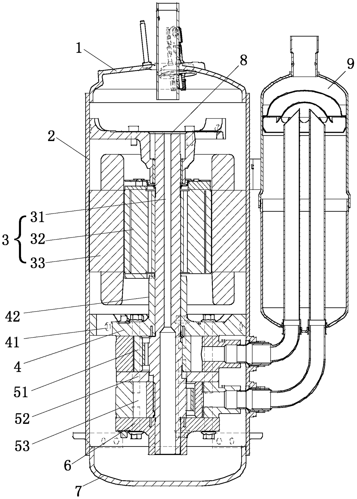
[0086] Such as figure 1 As shown, the upper and lower ends of the casing 2 in the rotary compressor of the present invention are respectively welded with the upper cover 1 and the lower cover 7 . The motor 3 is placed in the housing 2 , and the motor 3 includes an inner rotor 32 and an outer stator 33 sleeved on the crankshaft 31 . The outer stator 33 is fixed to the casing 2 . The inner rotor 32 is inserted into the outer stator 33 with a predetermined gap therebetween, and then rotates by interacting with the outer stator 33 . The crankshaft 31 is coupled to the inner rotor 32 to transmit the rotational force of the inner rotor 32 to the compression part 5 . The lower part of the crankshaft 31 is positioned on the central axis of the housing 2 by means of bearings (the lower support member 4 and the lower bearing 6 ). The lower support member 4 passes through the internal boss 42 structure ( Figure 4 Inner cylindrical structure) and the crankshaft 31 constitute a fricti...
no. 2 example
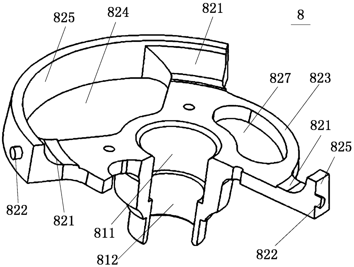
[0096] The second embodiment introduces a second structure of the upper support member 8 . Such as Figure 7 and 8 As shown, the difference between the second embodiment and the second embodiment is that the bearing part 81 and the flange part 82 in the second embodiment are not integral, and the bearing part 81 can be connected to the flange part 82 by screws 83, but This is not the limit.
[0097] In this embodiment, the bearing portion 81 includes three support arms 813 , but it is not limited thereto. The support arm 813 extends outward from the center of the bearing portion 81 . The flange portion 82 has three connection ports 828 . The outer end of the support arm 813 is screwed to the connection port 828 through the screw 83 . With the bearing portion 81 as the center of the circle, the intervals between the connecting ports 828 are 120 degrees, but not limited thereto. Among them, the three connection ports 828 are connected in a circular direction by an arc pane...
no. 3 example
[0102] The third embodiment introduces a third structure of the upper support member 8 . Such as Figure 10 and 11 As shown, the difference between the third embodiment and the first embodiment is that the bearing part 81 and the flange part 82 in the third embodiment are not integrated, and the bearing part 81 can be connected to the flange part 82 by screws 83, But not limited to this.
[0103]The third embodiment provides another combined structure of the upper support 8 . The flange portion 82 includes two sections of arc panels 825 , a ring portion 826 composed of reinforcing ribs 823 and four extending arms 829 . The ring portion 826 is sleeved on the outer periphery of the bearing portion 81 . The ring portion 826 is connected to two sections of arc panels 825 through the extension arms 829 , and the arc panels 825 are respectively located on both sides of the ring portion 826 . The upper end of the bearing portion 81 has an outwardly expanding shoulder 815 , the o...
PUM
 Abstract
Description
Claims
Application Information
 - R&D
- Intellectual Property
- Life Sciences
- Materials
- Tech Scout
- Unparalleled Data Quality
- Higher Quality Content
- 60% Fewer Hallucinations
Browse by: Latest US Patents, China's latest patents, Technical Efficacy Thesaurus, Application Domain, Technology Topic, Popular Technical Reports.
© 2025 PatSnap. All rights reserved.Legal|Privacy policy|Modern Slavery Act Transparency Statement|Sitemap|About US| Contact US: help@patsnap.com