Check patentability & draft patents in minutes with Patsnap Eureka AI!

Microwave UWB Antenna

An ultra-wideband antenna and microwave technology, applied in the field of antennas, can solve the problems of limited application occasions and large size, and achieve the effects of high radiation efficiency, good impedance matching, and good impedance matching.

Inactive Publication Date: 2020-04-28
SHENZHEN PROTRULY ELECTRONICS CO LTD
View PDF5 Cites 0 Cited by
  • Summary
  • Abstract
  • Description
  • Claims
  • Application Information

AI Technical Summary

Problems solved by technology

Typical ultra-wideband antennas include logarithmic periodic antennas, traveling wave antennas, horn antennas, etc. These antennas can achieve a working bandwidth of several octaves, but the disadvantage is that they are large in size and limited by the application

Method used


Image

  • Microwave UWB Antenna
  • Microwave UWB Antenna
  • Microwave UWB Antenna

Examples


Embodiment Construction

[0015] The present invention will be described in further detail below in conjunction with the embodiments and with reference to the accompanying drawings.

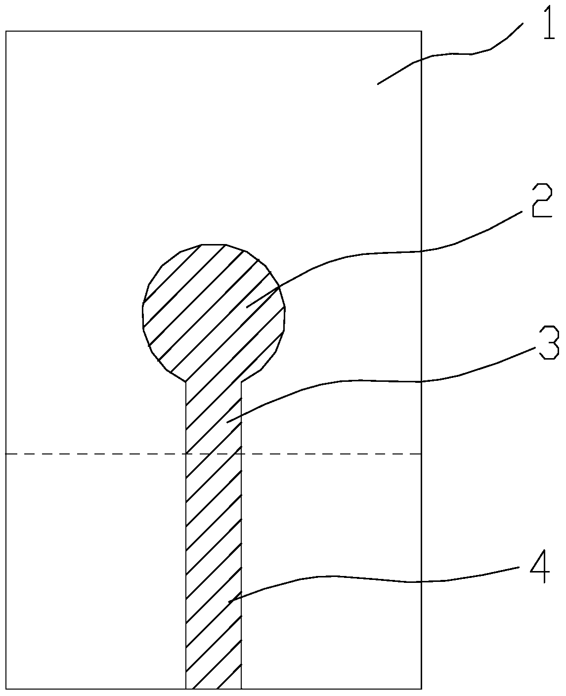
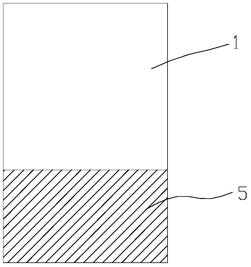
[0016] A microwave ultra-wideband antenna, such as figure 1 It is a structural diagram of the front of the antenna, including a dielectric substrate 1 with a size of 60mm×70mm and a thickness of 0.254mm-1.6mm. The middle of the front of the dielectric substrate 1 is covered with a circular metal sheet 2, and the rectangular metal patch 2 is connected. The metal conduction belt 4 is 5mm-40mm long and 0.5-3mm wide; figure 2 It is a structural schematic diagram of the back of the antenna. The back of the dielectric substrate 1 is covered with a rectangular metal grounding sheet 5 along one side, and the circular metal sheet 2 on the front of the dielectric substrate 1 radially extends a rectangular metal guide to one side of the metal grounding sheet 5 The strip 4 is electrically connected to the metal ground sheet 5 from ...


PUM


Abstract

The invention discloses a microwave ultra-wideband antenna which comprises a dielectric substrate. A round metal sheet is arranged on the central part of the dielectric substrate front in a covering way. A rectangular metal ground lug is arranged on the dielectric substrate back along a side in a covering way. The projection of the round metal sheet is separated from that of the metal ground lug. The round metal sheet on the front of the dielectric substrate extends radially towards one side of the metal ground lug and has a rectangular metal conduction band protrude and is further electrically connected with the metal ground lug from the edge of the dielectric substrate. The rectangular metal conduction band part connecting the projection of round metal sheet and the projection of the metal ground lug is a feed port band. The antenna which requires no special-purpose tools has the advantages of low echo loss, good impedance match and relatively wide impedance bandwidth.

Description

technical field [0001] The invention relates to an antenna, in particular to a microwave ultra-wideband antenna with small return loss, good impedance matching and wide impedance bandwidth. Background technique [0002] UWB, also known as impulse radio, dates back to the 19th century. UWB technology was originally developed as a military radar technology in 1960, and it was mainly used in the field of radar technology in the early days. Ultra-wideband means that the signal bandwidth is greater than 500MHz or the ratio of the signal bandwidth to the center frequency is greater than 25%. Unlike common communication methods that use continuous carrier waves, ultra-wideband uses extremely short pulse signals to transmit information, and usually the duration of each pulse is only tens of picoseconds to several nanoseconds. The bandwidth occupied by these pulses can even be as high as several GHz, so the maximum data transmission rate can reach hundreds of Mbps. At the same tim...

Claims


Application Information

Patent Timeline
Patent Type & Authority Patents(China)
IPC IPC(8): H01Q1/50H01Q1/38
Inventor 李翊钟崔林
Owner SHENZHEN PROTRULY ELECTRONICS CO LTD
Features
  • R&D
  • Intellectual Property
  • Life Sciences
  • Materials
  • Tech Scout
  • Unparalleled Data Quality
  • Higher Quality Content
  • 60% Fewer Hallucinations
Learn More