Check patentability & draft patents in minutes with Patsnap Eureka AI!

Magnetic linear or rotary encoders

A rotary encoder and encoder technology, which is applied in the direction of converting sensor output, instruments, and using electric/magnetic devices to transfer sensing components, etc., which can solve problems such as measurement result fluctuations and accuracy limitations

Active Publication Date: 2017-10-13
AVAGO TECH INT SALES PTE LTD
View PDF7 Cites 0 Cited by
  • Summary
  • Abstract
  • Description
  • Claims
  • Application Information

AI Technical Summary

Problems solved by technology

[0003] However, in actual operation, it is found that even if the ratio difference method is used, the measurement results will fluctuate due to environmental factors, so that the available accuracy is undesirably limited

Method used


Image

  • Magnetic linear or rotary encoders
  • Magnetic linear or rotary encoders
  • Magnetic linear or rotary encoders

Examples


Embodiment Construction

[0024] The same or corresponding parts are marked with the same symbols in the drawings, and these symbols are in image 3 , Figure 5 and Figure 6 The middle part has `. If expressions such as "upper", "lower" etc. are used in the following, they only refer to the illustrations in the relevant figures, since the linear or rotary encoder according to the invention can be used in any spatial orientation. It is expressly pointed out that, in order to illustrate important technical details, the drawings are not drawn to scale.

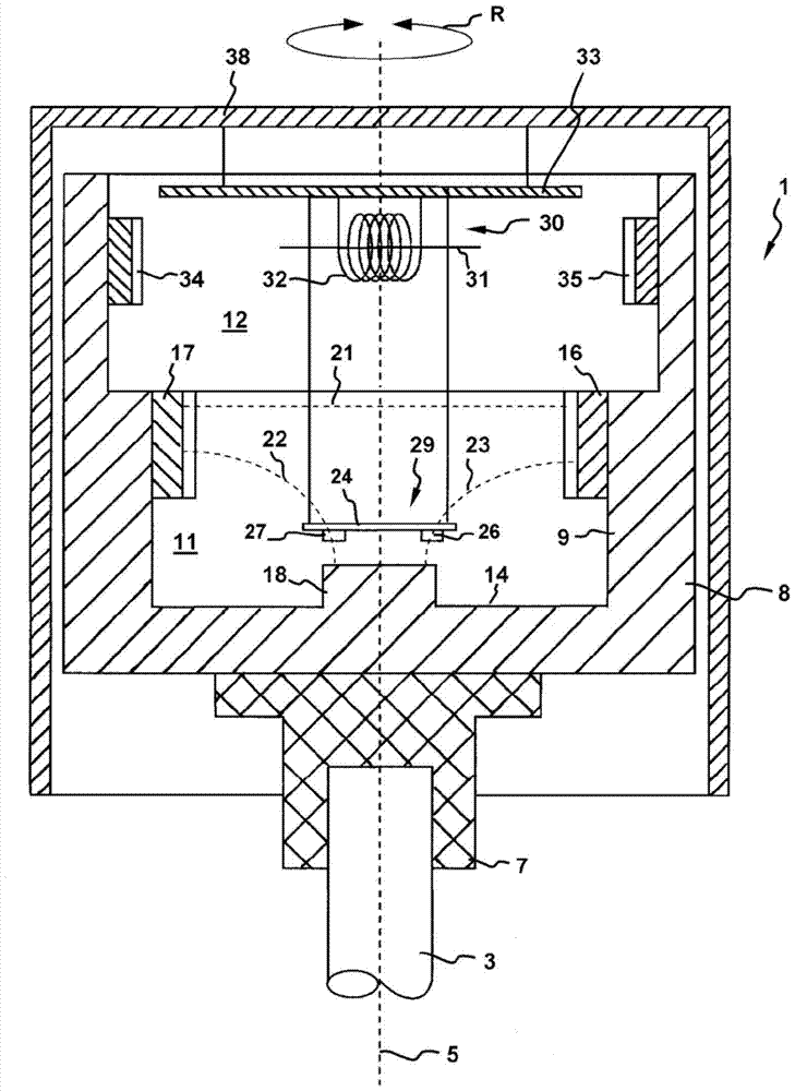
[0025] figure 1 A rotary encoder 1 is shown comprising a shaft body 3 which is rotatable about its central longitudinal axis 5 in both directions indicated by the double-headed arrow R. The shaft 3 can be the shaft to be monitored itself or an encoder shaft, which is mechanically coupled to the shaft, for example via a transmission, in such a way that it can unambiguously reproduce the rotational movement of the shaft actually to be monitored.

[00...


PUM


Abstract

A magnetic linear or rotary encoder (1) for detecting motion of an object comprising: an excitation unit (8) reproducing said motion and comprising at least one pair of oppositely arranged main permanent magnets (16, 17), said The main permanent magnets are magnetically connected via a ferromagnetic yoke (9) and form a measuring field space between said main permanent magnets; a high-resolution sensor unit (29; 29') for determining precise position values ​​is fixedly arranged and includes several magnetic field sensors (25, 26, 27, 28); and electronic processing equipment, which evaluates the signals of said high-resolution sensor units and includes a data memory, characterized in that a ferromagnetic deflector (18) is provided, At least a part of the magnetic field lines of the magnetic field generated by the main permanent magnet is deflected in a direction perpendicular to the magnetization vector of the main permanent magnet under the action of the deflector, and the high-resolution sensor unit is constructed and arranged such that it Each of the magnetic field sensors is passed by the vertical component of the magnetic flux deflected by the deflector, at least the yoke is made of heat-treated ferromagnetic material, and the high-resolution sensor unit does not contain ferromagnetic components.

Description

technical field [0001] The invention relates to a magnetic linear or rotary encoder of the type stated in the preamble of claim 1 . Such encoders are described, for example, in laid-open publications DE 10 2007 039 050 A1 and DE 10 2010 022 154 A1. Background technique [0002] DE 10 2009 023 515 A1 and DE 10 2010 010 560 in connection with similar encoders point out that in order to obtain highly precise measurement results it is necessary to determine the magnetic field values ​​which characterize the relevant position by means of e.g. Four measured values ​​to form two differences and form a quotient from these two differences (ratio-difference method), thus eliminating superimposed disturbance variables (such as an external magnetic field superimposed on the measuring field) and multiplying disturbance variables (such as the relationship with temperature related drift phenomenon). In theory, the application of this method is indeed a necessary condition for obtaining h...

Claims


Application Information

Patent Timeline
Patent Type & Authority Patents(China)
IPC IPC(8): G01D5/14G01D3/036
CPCG01D3/036G01D5/145G01D2205/26G01D2205/40G01D5/2216
Inventor 沃尔特·梅纳特托马斯·泰尔
Owner AVAGO TECH INT SALES PTE LTD
Features
  • R&D
  • Intellectual Property
  • Life Sciences
  • Materials
  • Tech Scout
  • Unparalleled Data Quality
  • Higher Quality Content
  • 60% Fewer Hallucinations
Learn More