Double-drill-bit bench drill with automatic feeding mechanism
A technology of automatic feeding and double-head bench drilling, which is applied in the directions of driving devices, manufacturing tools, boring/drilling, etc., can solve the problems of slow processing efficiency and increased process difficulty, and achieve the goal of improving processing efficiency and reducing process difficulty Effect
- Summary
- Abstract
- Description
- Claims
- Application Information
AI Technical Summary
Problems solved by technology
Method used
Image

Examples
Embodiment 1)
[0023] Figure 1 to Figure 9 One specific embodiment of the invention is shown.
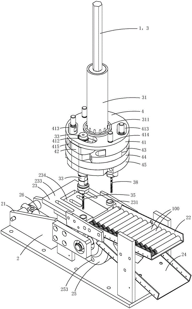
[0024] This embodiment is a kind of automatic feeding double drill bench drill, see Figure 1 to Figure 9 As shown, the bench drill includes a bench drill body 1 and a feeding mechanism 2 .
[0025] The bench drill body 1 includes a double drill mechanism 3 and a lifting mechanism (not shown in the figure) for driving the double drill mechanism 3 to move up and down.
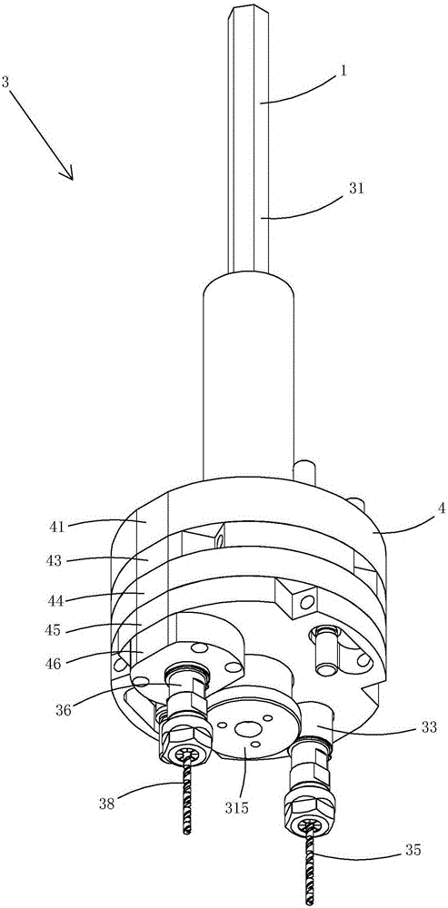
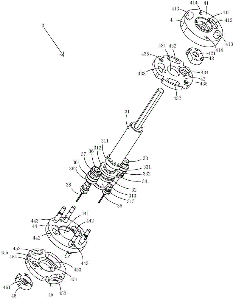
[0026] See Figure 1 to Figure 4 As shown, the double drill mechanism 3 includes a mounting plate 4, a main shaft 31 that is rotatably arranged at the center of the mounting plate, a driving wheel 32 that is fixed on the main shaft, a first transmission shaft 33 that is rotatably disposed on the mounting plate, and is fixedly arranged on the first The first driven wheel 34 at the upper end of the transmission shaft, the first drill bit 35 arranged at the lower end of the first transmission shaft, the second transmission shaft 36...
Embodiment 2)
[0060] Figure 10 to Figure 12 A second specific application embodiment of the invention is shown.
[0061] This embodiment is basically the same as Embodiment 1, the difference is: see Figure 10 to Figure 12 As shown, this embodiment no longer sets the cylinder and the pin shaft, but directly uses a geared motor (not shown in the figure) to drive the reciprocating rotation of the feed wheel; specifically, the geared motor can be used to directly drive the shaft of the feed wheel to rotate In addition, a plurality of travel switches can be provided on the frame body, and a plurality of triggers for triggering a corresponding travel switch can be set on the material transfer wheel, so that the position of the transfer wheel can be judged by the trigger status of each travel switch. Position, to automatically control the operation of the geared motor, that is, to realize the automatic operation of the control material transfer wheel; through this structure, ordinary motors can...
specific Embodiment approach
[0064] This embodiment is basically the same as Embodiment 1, the difference is: see Figure 13 to Figure 16 As shown, the shape of the trough in this embodiment is U-shaped; the material transfer wheel in this embodiment is provided with a first slide block 51 and a first guide rail 52 adapted to the first slide rail for driving the first slide rail. A material clamping cylinder 53 for reciprocating sliding of a slider, a second slider 54, a second guide rail 55 adapted to the second slider, and a discharge cylinder 56 for driving the second slider to reciprocate and slide.
[0065] When the trough is located directly below the through hole on the blocking member, the first guide rail 52 is set along the horizontal direction, and the material clamping cylinder can drive the first slider to move back and forth along the horizontal direction, and clamp or loosen the workpiece during the moving process ; The second guide rail is set along the vertical direction, and the discharg...
PUM
 Abstract
Description
Claims
Application Information
 - R&D Engineer
- R&D Manager
- IP Professional
- Industry Leading Data Capabilities
- Powerful AI technology
- Patent DNA Extraction
Browse by: Latest US Patents, China's latest patents, Technical Efficacy Thesaurus, Application Domain, Technology Topic.
© 2024 PatSnap. All rights reserved.Legal|Privacy policy|Modern Slavery Act Transparency Statement|Sitemap