
Finger mechanism of wiring robot

A robot finger and wiring technology, applied in the field of robots, can solve the problems of slow wiring operation, cumbersome wiring work, complex electrical system, etc., and achieve the effect of large wiring and wiring workload, improving wiring efficiency, and accurate wiring operation.

Inactive Publication Date: 2016-02-03
上海交通大学无锡研究院
View PDF6 Cites 6 Cited by
  • Summary
  • Abstract
  • Description
  • Claims
  • Application Information

AI Technical Summary

Problems solved by technology

[0002] Conventional electrical wiring is done by manual wiring, which is a highly repetitive and cumbersome operation
Manual wiring operation is prone to wrong wiring, and the quality of wiring cannot be guaranteed, especially for complex electrical systems. There can be hundreds or even thousands of wiring terminals in electrical cabinets. Wiring personnel perform wiring and wiring according to electrical diagrams. Slow, the cycle is very long; at the same time, the wiring work is prone to errors such as misconnection, missing connection, virtual connection, etc. If there is a short circuit, the electronic device may be burned directly
Therefore, error checking is required before the system runs, and equipment debugging is very difficult, resulting in an unguaranteed system development and manufacturing cycle and delays in production. In addition, due to quality problems in manual wiring, electrical failures may occur after the system runs, which will lead to large economic losses. loss

Method used


Image

  • Finger mechanism of wiring robot
  • Finger mechanism of wiring robot
  • Finger mechanism of wiring robot

Examples


Embodiment Construction

[0021] The present invention will be further described below in conjunction with specific drawings and embodiments.

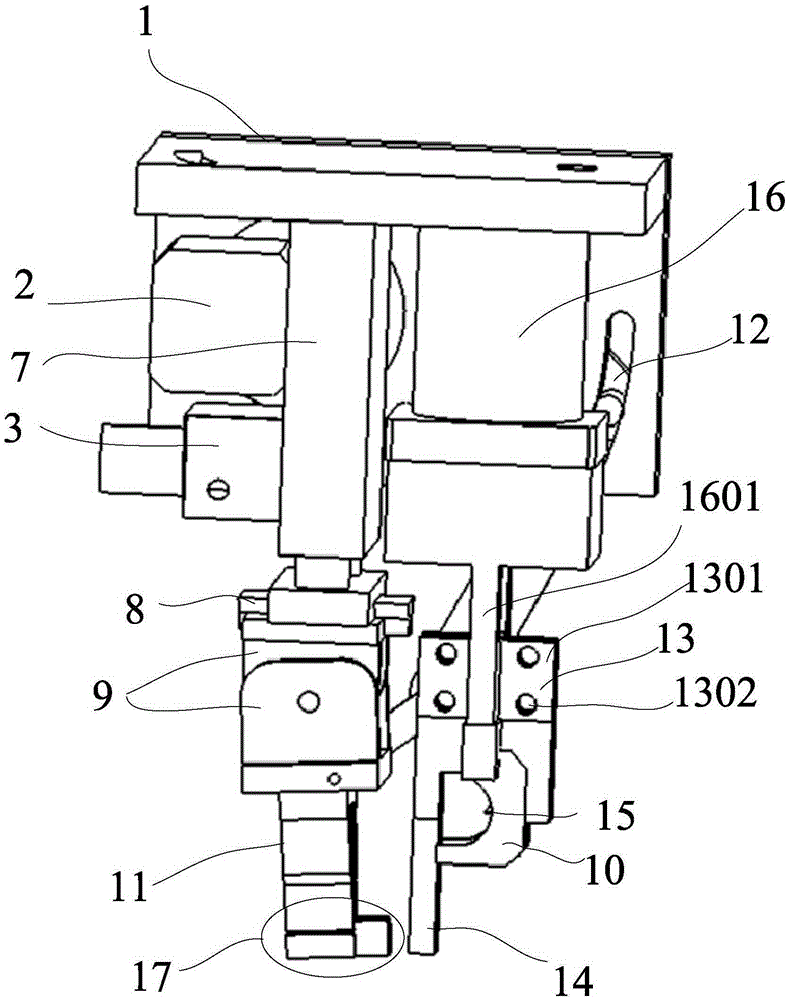
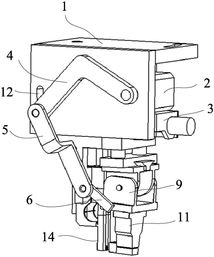
[0022] A wiring robot finger mechanism provided in this embodiment, such as figure 1 and figure 2 shown, including:

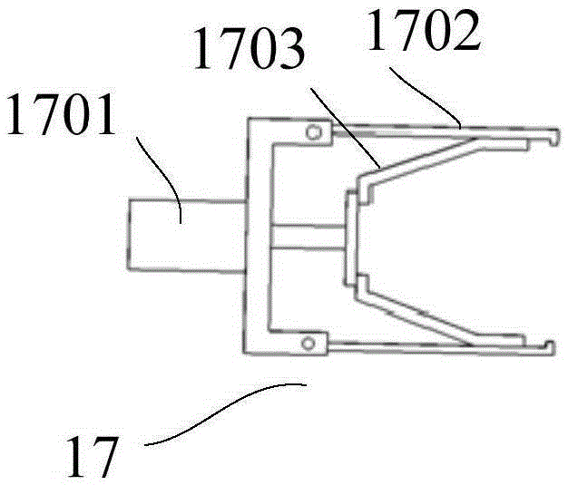
[0023] Mounting plate 1, stepping motor 2, wire feeder 3, swing connecting rod 4, angle connecting rod 5, lifting connecting rod 6, telescopic cylinder 7, slider 8, movable joint 9, wire passing device 10, wire stripping mechanism 11 , slideway 12, compression spring opening and closing bin 13, clamping finger 14, thread cutter 15, rotary drive cylinder 16, wire stripping nozzle 17;

[0024] The mounting plate 1 is used to connect the arm mechanism above the finger mechanism of the wiring robot. The arm mechanism is not within the scope of the present invention, and its structure is not given. It should be noted that the movement of the arm mechanism can drive the installation plate 1 to move or rotate, thereby driving the entire finger mech...


PUM


Abstract

The invention provides a finger mechanism of a wiring robot. The finger mechanism of the wiring robot comprises a mounting plate, a stepping motor, a wire feeder, an oscillating connection rod, an angle connection rod, a lifting connection rod, a telescopic air cylinder, a sliding block, a movable joint, a wire passing device, a wire stripping mechanism, a slide way, a compression spring turn on-off bin, clamping fingers, a wire cutter, a rotating drive air cylinder and a wire stripping nozzle, wherein the stepping motor and the telescopic air cylinder are mounted on one side of the mounting plate; the lower end of the telescopic air cylinder is in sliding connection with the sliding block; the sliding block is connected with the upper end of the movable joint, and the lower end of the movable joint is connected with the wire stripping mechanism; the lower end of the wire stripping mechanism is provided with the wire stripping nozzle; the stepping motor is connected with the lower end of the movable joint through a connection rod mechanism; the rotating drive air cylinder is mounted on the mounting plate; two air claws at the lower end of the rotating drive air cylinder are connected with the compression spring turn on-off bin respectively; and the lower end of the compression spring turn on-off bin is connected with the two clamping fingers. By means of the finger mechanism of the wiring robot, the wiring quality of electric appliances can be ensured, and the production efficiency is improved.

Description

technical field [0001] The invention relates to a robot, especially a robot for wiring. Background technique [0002] Conventional electrical wiring is done by manual wiring, which is a highly repetitive and cumbersome operation. Manual wiring operation is prone to wrong wiring, and the quality of wiring cannot be guaranteed, especially for complex electrical systems. There can be hundreds or even thousands of wiring terminals in electrical cabinets. Wiring personnel perform wiring and wiring according to electrical diagrams. Slow, the cycle is very long; at the same time, the wiring work is prone to errors such as misconnection, missing connection, virtual connection, etc. If there is a short circuit, the electronic device may be directly burned out. Therefore, error checking is required before the system runs, and equipment debugging is very difficult, resulting in an unguaranteed system development and manufacturing cycle and delays in production. In addition, due to qua...

Claims


Application Information

Patent Timeline
IPC IPC(8): B25J15/00
Inventor 陈自强陆崇清陈伊冉
Owner 上海交通大学无锡研究院
Features
  • Generate Ideas
  • Intellectual Property
  • Life Sciences
  • Materials
  • Tech Scout
  • Unparalleled Data Quality
  • Higher Quality Content
  • 60% Fewer Hallucinations
Learn More