
Prefabricated assembled type steel-concrete combined beam connected through bolt nails

A prefabricated assembly and reinforced concrete technology, applied to building components, floor slabs, buildings, etc., can solve the problems of high energy consumption in the whole building cycle, unstable construction quality, complicated construction procedures, etc., and achieve good resistance to horizontal shearing and pulling Power, good promotion value, shortening the effect of construction time

Inactive Publication Date: 2016-02-03
HUNAN UNIV
View PDF7 Cites 19 Cited by
  • Summary
  • Abstract
  • Description
  • Claims
  • Application Information

AI Technical Summary

Problems solved by technology

[0005] The connection structure between the traditional concrete floor and H-shaped steel beams and the connection structure between cast-in-place reinforced concrete and beams are difficult to construct, the construction process is complicated, the amount of materials is large, the construction quality is unstable, and the energy consumption in the whole cycle of the building is high.

Method used


Image

  • Prefabricated assembled type steel-concrete combined beam connected through bolt nails
  • Prefabricated assembled type steel-concrete combined beam connected through bolt nails
  • Prefabricated assembled type steel-concrete combined beam connected through bolt nails

Examples


Embodiment 1

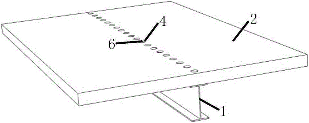
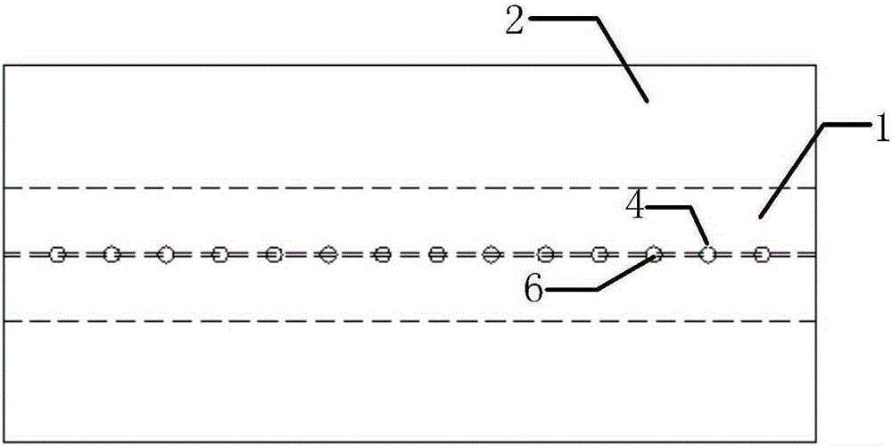
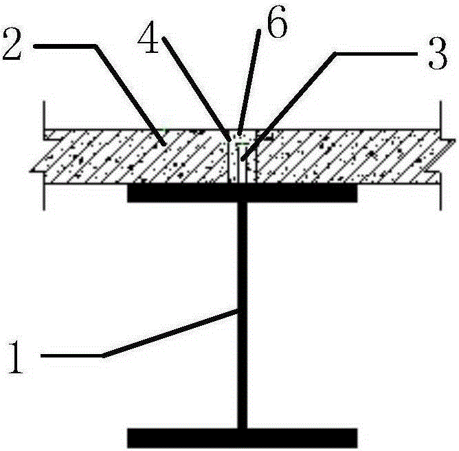
[0032] A prefabricated steel-concrete composite beam connected by studs, such as Figure 1~4 As shown, the connection structure is composed of H-shaped steel beams 1, prefabricated reinforced concrete floors 2, shear stud connectors 3, reserved circular through holes 4 for prefabricated floors, and non-shrinkage self-compacting high-strength concrete filler 6. The upper flange of the H-shaped steel beam 1 is welded with shear studs 3 on the center line along the beam axis direction according to design requirements, and the prefabricated reinforced concrete floor slab 2 is provided with circular reserved through holes 4 corresponding to the positions of the studs. When applied in the construction process, after the H-shaped steel beam 1 and the prefabricated reinforced concrete floor 2 are hoisted and docked, the non-shrinkage self-compacting high-strength concrete filler 6 is poured into the circular reserved through hole 4 . The non-shrinkage self-compacting high-strength con...

Embodiment 2

[0034] A prefabricated steel-concrete composite beam connected by studs, such as Figure 5-8 As shown, the difference from Embodiment 1 is only that double rows of shear studs 3 are welded along the axial direction of the beam at the left-right symmetrical position of the center line of the upper flange of the H-shaped steel beam 1, and the prefabricated reinforced concrete floor 2 is provided with Double rows of circular reserved through holes 4 corresponding to the positions of the studs.

Embodiment 3

[0036] A prefabricated steel-concrete composite beam connected by studs, such as Figures 9 to 12 As shown, the difference from Embodiment 1 is only that double rows of shear studs 3 are welded along the axial direction of the beam at the left-right symmetrical position of the center line of the upper flange of the H-shaped steel beam 1, and the prefabricated reinforced concrete floor 2 is provided with A square reserved through hole 5 corresponding to the peg position.


PUM


Abstract

The invention provides a prefabricated assembled type steel-concrete combined beam connected through studs. The prefabricated assembled type steel-concrete combined beam connected through studs comprises an H-shaped steel beam which is formed by welding steel sheets, and shear bolt nails are welded to the upper wing edge of the steel beam; the prefabricated assembled type steel-concrete combined beam further comprises a prefabricated reinforced concrete floor, and through holes corresponding to the steel beam in position are reserved in the floor. After the steel beam and the prefabricated reinforced concrete floor are hoisted and docked, non-shrinkage self-compacting high-intensity concrete filler is poured into the holes, and integrated connection between the steel steam and the reinforced concrete floor is achieved. Good adhesion between the non-shrinkage self-compacting high-intensity concrete filler and the bolt nails is achieved, the bolt nails can have good horizontal shear resistance and drawing force resistance, and meanwhile the whole structure has good ductility and anti-seismic property. According to the prefabricated assembled type steel-concrete combined beam connected through studs, all components are prefabricated in a factory, assembling and connection are conducted at a construction site, site wet operation is reduced, project quality is guaranteed, the construction cycle is shortened, the assembling efficiency of building industrialization is improved, and social and economic benefits are good.

Description

technical field [0001] The invention belongs to the field of connection structure of building components, and is particularly applicable to the beam-slab connection structure of a multi-story steel-concrete composite structure assembled residence. Background technique [0002] my country began to realize the application of construction industrialization in the 1950s, drawing on the technical system of the former Soviet Union, and promoting the development of prefabricated components and prefabricated buildings in industrial plants and residences. By the 1980s, prefabricated concrete components had achieved good research results and development trends, but limited to the economic conditions and technical level at that time, prefabricated buildings have not been widely used. After the 1990s, due to the emergence of a large number of cheap labor and the development of commercial concrete technology, the application of prefabricated buildings in civil buildings continued to decr...

Claims


Application Information

Patent Timeline
IPC IPC(8): E04B5/10
Inventor 霍静思钟琼王海涛
Owner HUNAN UNIV
Learn More