Check patentability & draft patents in minutes with Patsnap Eureka AI!

Applicable to the method of changing the steel derrick to the well tower in the underground mining hoisting system

A hoisting system and underground mining technology, applied in shaft equipment, mining equipment, earth-moving drilling, etc., can solve the problems of easy slippage of the first rope, easy freezing of the crown wheel and the first rope, hidden safety hazards, etc. The effect of strong safety and reliability and construction quality assurance

Active Publication Date: 2017-09-19
CINF ENG CO LTD
View PDF3 Cites 0 Cited by
  • Summary
  • Abstract
  • Description
  • Claims
  • Application Information

AI Technical Summary

Problems solved by technology

[0002] The auxiliary shaft is the only channel for production personnel, materials, and equipment to go up and down the mine. The supporting structures of the existing auxiliary shaft hoisting system generally include a derrick and a well tower. The advantages of the derrick are simple structure and less investment. In cold and wet weather in winter, when the hoisting system stops running, the top wheel and the first rope are likely to freeze. If not handled in time, the first rope is easy to slip, which poses a great safety hazard to the operation of the auxiliary shaft, especially when people go up and down the shaft.
With the improvement of people's safety awareness and the expansion of production scale, a considerable number of derricks can no longer meet the needs of safety and production, and hope to transform them into well towers
If the conventional method of reconstruction and expansion is followed, that is, the original steel derrick is dismantled first, and then the reinforced concrete well tower is built, and then the equipment is installed and debugged. After the new lifting system of the auxiliary shaft is completed and put into production, the mine will stop production for at least one year. mine unacceptable

Method used


Image

  • Applicable to the method of changing the steel derrick to the well tower in the underground mining hoisting system
  • Applicable to the method of changing the steel derrick to the well tower in the underground mining hoisting system
  • Applicable to the method of changing the steel derrick to the well tower in the underground mining hoisting system

Examples


Embodiment Construction

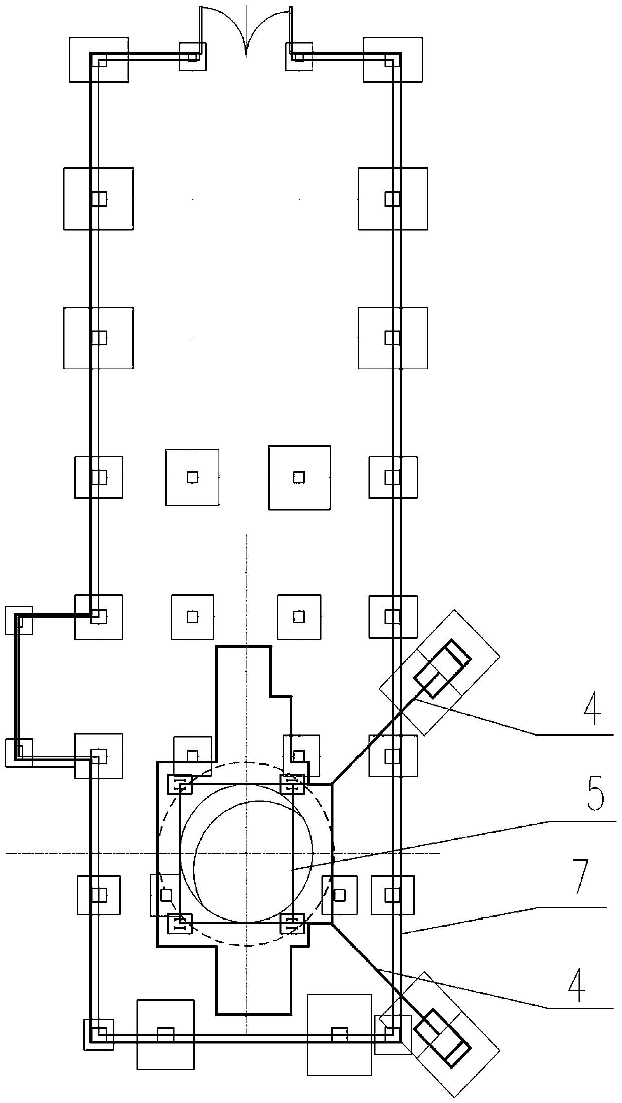
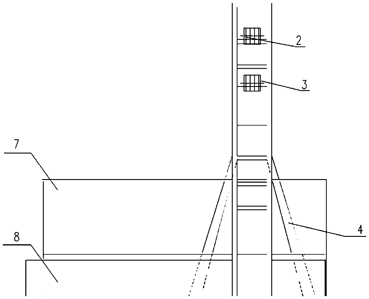
[0032] figure 1 and figure 2 It is a common and representative oblique bracing steel derrick structure in the existing steel derrick. It generally includes the original steel derrick lifting device 1, the original steel derrick upper sky wheel 2, the original steel derrick lower sky wheel 3, the original steel derrick diagonal brace 4, the original steel derrick vertical frame 5, the original steel wire rope 6, the original wellhead room 7, etc. Generally, the derrick is divided into 4 platform layers: the upper sky wheel platform ①, the lower sky wheel platform ②, the top platform of the vertical frame ④, and the wellhead platform (ground) ⑥. For example, the auxiliary shaft hoisting system of a gold-copper mine in Hubei is currently using this kind of diagonally braced steel derrick. The plane projection size of the main part of the derrick is 6.5m×9m, and the height is 35m. The center elevation of the upper sky wheel is 57.1m, and the center elevation of the lower sky whe...


PUM


Abstract

The invention discloses a method suitable for converting a steel well frame into a well tower for an underground mining lifting system. The method includes the steps of firstly, determining a containing type well tower design scheme; secondly, conducting implementation step by step according to the scheme; thirdly, erecting a steel-structure safety channel for lifting up and putting down personnel, materials and devices on a deputy wellhead, safely isolating a deputy well lifting steel well frame from a head sheave through a steel plate, closing a steel wire rope running channel from the head sheave to a lifting machine room through a scaffold and a scaffold floor layer by layer, and detaching a hoisting framework and a lodge room on the top of an existing steel well frame. By means of the method, the well tower can be newly established under the condition that the deputy well lifting steel well frame does not shut down, and after the well tower civil engineering building project is completed and a lifting device is installed and adjusted, an upper head sheave, a lower head sheave and an inclined support of the existing steel well frame are detached. A vertical frame of the existing steel well frame extends to a cage blocking beam of the well tower, and a steel inner frame of the well tower is formed. After rope hanging, cage descending and adjusting, the well tower can be used for production run.

Description

technical field [0001] The invention belongs to the technical field of mining engineering, and in particular relates to a method suitable for changing a steel derrick into a well tower in an underground mining lifting system. Background technique [0002] The auxiliary shaft is the only channel for production personnel, materials, and equipment to go up and down the mine. The supporting structures of the existing auxiliary shaft hoisting system generally include a derrick and a well tower. The advantages of the derrick are simple structure and less investment. In cold and wet weather in winter, when the hoisting system is stopped, the top wheel and the first rope are prone to freeze. If not handled in time, the first rope is easy to slip, which poses a great safety hazard to the operation of the auxiliary shaft, especially for people going up and down the shaft. With the improvement of people's safety awareness and the expansion of production scale, a considerable number of ...

Claims


Application Information

Patent Timeline
Patent Type & Authority Patents(China)
IPC IPC(8): E21D7/00
Inventor 陈建双葛文杰朱旭红郭斌
Owner CINF ENG CO LTD
Features
  • R&D
  • Intellectual Property
  • Life Sciences
  • Materials
  • Tech Scout
  • Unparalleled Data Quality
  • Higher Quality Content
  • 60% Fewer Hallucinations
Learn More