
Solar-powered branch shearing device for cuttage
A technology of solar power supply and shearing device, which is applied in the field of agriculture and forestry, can solve the problems of misalignment of the predetermined cutting position of branches, low efficiency, and difficulty in forming cutting and forming parts, etc., and achieve the effects of simple and stable device structure, improving work efficiency and reducing production costs
- Summary
- Abstract
- Description
- Claims
- Application Information
AI Technical Summary
Problems solved by technology
Method used
Image

Examples
Embodiment Construction
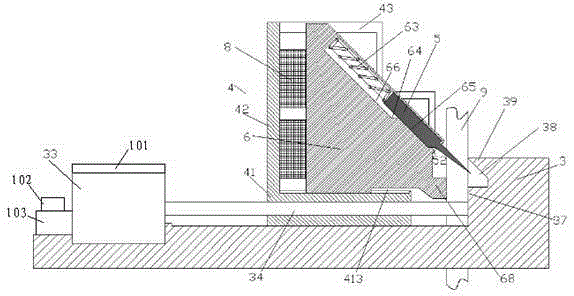
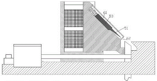
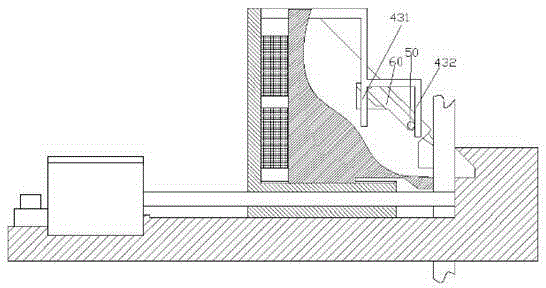
[0013] Combine below Figure 1-4 The present invention will be described in detail.
[0014] According to an embodiment, a solar-powered cuttage cutting device includes a frame 3, a motor 33 fixedly mounted on the frame 3 driven by a screw 34 and able to slide on the frame 3. frame 4 and the clamping slope block 6 installed on the sliding frame 4, wherein the sliding frame 4 includes a horizontal part 41 threadedly fitted with the screw rod 34, and a vertical part fixedly connected with the horizontal part 41 42 and a toggle part 43 fixedly connected to the vertical part 42 at the front and rear sides of the clamping ramp block 6, wherein the bottom of the clamping ramp block 6 is slidably installed on the horizontal In the chute 413 on the upper side of the part 41, a compression elastic member 8 is provided between the vertical part 42 and the left side of the clamping ramp block 6 to place the clamping ramp block 6 in the Biased to the right in the chute 413, the bottom r...
PUM
 Abstract
Description
Claims
Application Information