Valve seat structure of abrasion-resistant ball valve

A wear-resistant ball and valve seat technology, which is applied to valve devices, cocks including cut-off devices, engine components, etc., can solve the problems of valve leakage, spring stuck, loss of elasticity, etc., and achieve short service life and good sealing performance , long service life effect

Inactive Publication Date: 2016-02-17
TIANJIN BAILIZHANFA GRP
View PDF7 Cites 3 Cited by
  • Summary
  • Abstract
  • Description
  • Claims
  • Application Information

AI Technical Summary

Problems solved by technology

[0002] At present, the back of the existing wear-resistant ball valve seat is pre-tightened by a cylindrical spring, and solid particles i

Method used


Image

  • Valve seat structure of abrasion-resistant ball valve

Examples


Example Embodiment

[0015] The present invention will be further described in detail below in conjunction with the accompanying drawings and through specific embodiments. The following embodiments are only descriptive, not restrictive, and cannot limit the protection scope of the present invention.

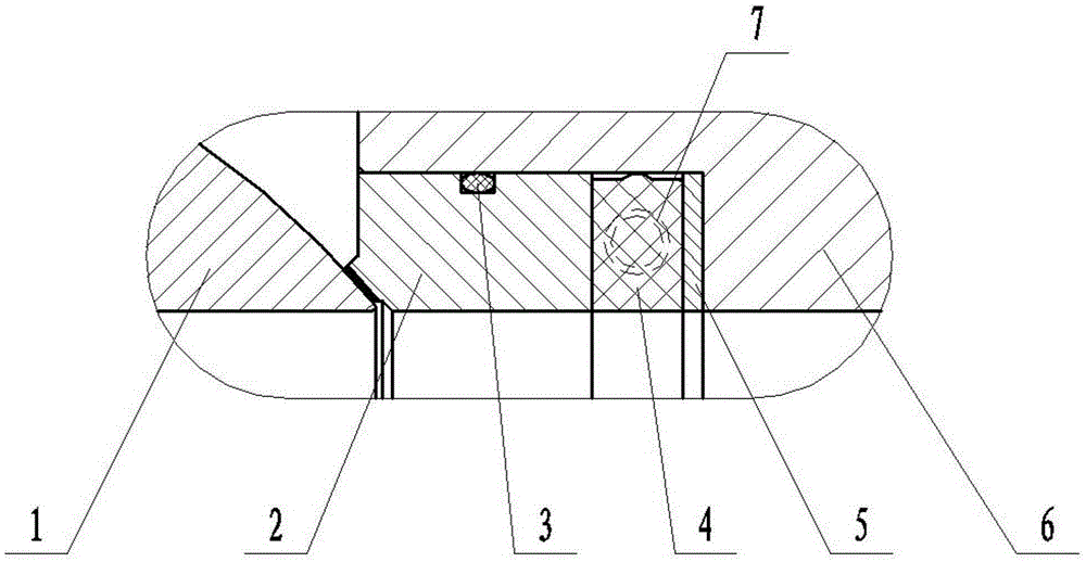
[0016] A seat structure of a wear-resistant ball valve, including a valve body 6, a ball 1, a valve seat 2 and an O-ring 3, a ball is installed in rotation in the valve body, and a valve seat installation ring groove is formed in the valve body at the contact position of the ball, And a valve seat coaxial with the flow channel is press-fitted in the installation ring groove, and the sealing surface of the valve seat and the ball is in metal sealing contact;

[0017] An O-ring is installed coaxially in the middle of the radial contact surface between the valve seat and the valve body;

[0018] The innovation of this structure lies in:

[0019] A rubber ring 4 is installed coaxially between the axial ...


PUM


Abstract

The invention relates to a valve seat structure of an abrasion-resistant ball valve. The valve seat structure comprises a valve body, a ball body, a valve seat body and an O-shaped ring. The ball body is rotatably installed in the valve body. An annular valve seat installing groove is formed in the position, making contact with the ball body, in the valve body. The valve seat body coaxial with a flow channel is installed in the annular installing groove in a pressed mode. A sealing face between the valve seat body and the ball body is in a metal sealed contact mode. The O-shaped ring is coaxially installed in the middle of the radial contact surface between the valve seat body and the valve body in a limited mode. A rubber ring is coaxially installed between the axial contact surfaces between the valve seat body and the valve body. A radial convex ring is arranged in the middle of the outer peripheral surface of the rubber ring. A gasket is coaxially installed between the axial contact surfaces between the rubber ring and the valve body. According to the valve seat structure of the abrasion-resistant ball valve, the service life of the valve is long, the sealing performance is good, and the problems that a ball valve is short in service life and prone to leakage are effectively solved.

Description

technical field [0001] The invention belongs to the field of valves and relates to ball valves, in particular to a wear-resistant ball valve seat structure. Background technique [0002] At present, the back of the seat of the existing wear-resistant ball valve is pre-tightened by a cylindrical spring, and solid particles in the medium are easily deposited on the spring, causing the spring to be stuck and lose its elasticity, resulting in leakage of the valve. [0003] After searching, the following published technologies in similar technical fields were found: [0004] A self-tightening packing seal structure of a ball valve seat (CN204647401U), including a ball, a valve seat, a packing, a pressure ring inside a valve seat packing, a spring, a pressure ring outside a valve seat packing, a dustproof ring, and a side valve body; The ball is installed in the valve seat, and the valve seat is installed in the side valve body; the joint between the valve seat and the side valve...

Claims


Application Information

Patent Timeline
IPC IPC(8): F16K5/06F16K5/08
CPCF16K5/0673F16K5/0689
Inventor 宋保明崔园园李永超李朋
Owner TIANJIN BAILIZHANFA GRP
Why Eureka
Try Eureka