Embedded composite damping structure and construction method thereof
A composite damping and damping structure technology, which is applied in basic structure engineering, protection devices, buildings, etc., can solve problems such as unfavorable vibration isolation trench load-bearing and collapse, achieve low production cost, attenuate noise and vibration transmission, reduce vibration and vibration. Effects of Noise Pollution
- Summary
- Abstract
- Description
- Claims
- Application Information
AI Technical Summary
Problems solved by technology
Method used
Image

Examples
Embodiment 1
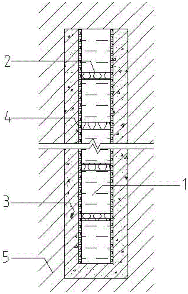
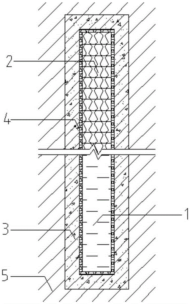
[0034] An embedded composite damping structure, comprising a multi-layer damping structure placed in a trench, a reinforced concrete layer 3 located on the side walls and bottom of the trench, and a viscoelastic damping layer II4; the viscoelastic damping layer II4 is located on the reinforced concrete Between layer 3 and the multilayer damping structure. The multi-layer damping structure includes a constrained layer 1 and a viscoelastic damping layer I2, and a viscoelastic damping layer I2 is arranged between two adjacent constrained layers 1; the viscoelastic damping layer I2 and the viscoelastic damping layer II4 It is a spray-on composite damping material. In the present invention, two constrained layers 1 and the damping layer I2 therebetween form a constrained damping structural unit, and a plurality of constrained damping structural units are superimposed to form a multi-layer damping structure for vibration in the vertical direction; the reinforced concrete layer 3 and...
Embodiment 2
[0045] Different from Example 1, the thickness ratio of the viscoelastic damping layer I2 to the constrained layer 1 is 1:800; the number of the constrained layer 1 is not less than 2; the thickness of the constrained layer 1 is 120 cm, and the The thickness of the viscoelastic damping layer I2 is 15 mm, and the thickness of the viscoelastic damping layer II4 is 2 mm. The constrained layer 1 is reinforced concrete.
[0046] Wherein, the spray-on composite damping material is obtained by reacting two components A and R according to a volume ratio of 1:0.8. The A component is a semi-prepolymer synthesized by 45 parts of low-functionality polyisocyanate and 70 parts of polyether polyol; the R component includes 15 parts of diamine chain extender, 40 parts of amino-terminated polyether, 70 parts of hydroxyl-terminated polyether, 1 part of intercalated graphite filler, and 15 parts of additives. The low-functionality polyisocyanate is 4,4'-diphenylmethane diisocyanate modified by...
Embodiment 3
[0055] Different from Example 1, the thickness ratio of the viscoelastic damping layer I2 and the constrained layer 1 is 1:50; the number of the constrained layer 1 is not less than 2; the thickness of the constrained layer 1 is 5 cm, and the The thickness of the viscoelastic damping layer I2 and the viscoelastic damping layer II4 is 1 mm. The constrained layer 1 is marble.
[0056] Wherein, the spray-on composite damping material is obtained by reacting two components A and R according to a volume ratio of 1:1.2. The spray-on composite damping material is obtained by reacting two components A and R according to 1:1, and the A component is a semi-prepolymer synthesized from 60 parts of low-functionality polyisocyanate and 50 parts of polyether polyol ; The R component includes 35 parts of diamine chain extender, 75 parts of amino-terminated polyether, 10 parts of hydroxyl-terminated polyether, 16 parts of intercalated graphite filler, and 30 parts of auxiliary agent. The low...
PUM
| Property | Measurement | Unit |
|---|---|---|
| Thickness | aaaaa | aaaaa |
| Thickness | aaaaa | aaaaa |
| Thickness | aaaaa | aaaaa |
Abstract
Description
Claims
Application Information
 - R&D Engineer
- R&D Manager
- IP Professional
- Industry Leading Data Capabilities
- Powerful AI technology
- Patent DNA Extraction
Browse by: Latest US Patents, China's latest patents, Technical Efficacy Thesaurus, Application Domain, Technology Topic.
© 2024 PatSnap. All rights reserved.Legal|Privacy policy|Modern Slavery Act Transparency Statement|Sitemap