This helps you quickly interpret patents by identifying the three key elements:
Problems solved by technology
Method used
Benefits of technology
Problems solved by technology
Therefore, in a DC / DC converter having an intermittent oscillation operation function, intermittent oscillation may become impossible
[0011] In addition, in the electronic device described in Document 2, the structure of the device becomes complicated
Method used
Image
Click on the blue label to locate the original text in one second.
Reading with bidirectional positioning of images and text.
Examples
Embodiment approach
[0032] First, the overall configuration of the image forming apparatus according to the present embodiment will be described.
[0033] [Overall structure of image forming apparatus]
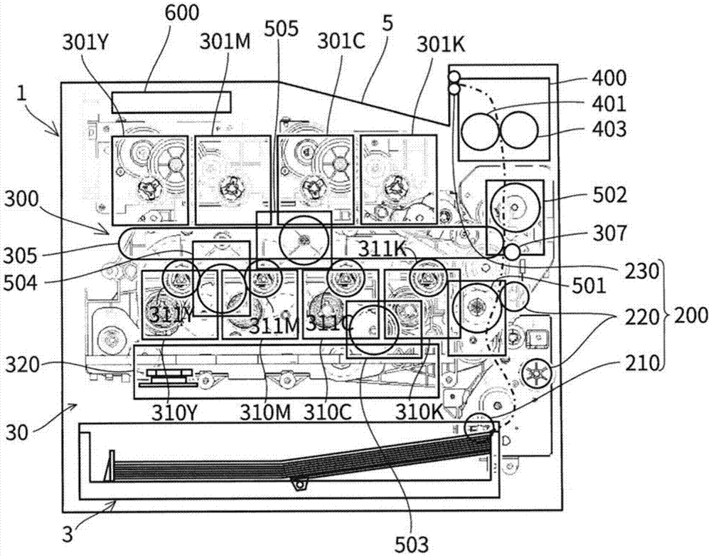
[0034] figure 1 It is a side view showing the hardware configuration of the image forming apparatus in one embodiment of the present invention.
[0035] Referring to the drawing, the image forming apparatus 1 includes a paper feed cassette 3 , a paper output tray 5 , a printer unit 30 , and a power supply unit (an example of a power supply control unit) 600 .
[0036] The sheet feeding cassette 3 is detachably arranged in the casing of the image forming apparatus 1 at the lower portion of the image forming apparatus 1 . When printing, the paper loaded in each paper feeding cassette 3 is fed from the paper feeding cassette 3 one by one, and sent out to the printing unit 30 . The number of paper feeding cassettes 3 is not limited to one, and may be more than one.
[0037] The paper discharge tr...
no. 2 Embodiment approach
[0128] The basic configuration of the image forming apparatus 1 and the basic configuration of the power supply unit in the second embodiment are the same as those in the first embodiment, and therefore, the description here will not be repeated. The second embodiment differs from the first embodiment in that, in the power supply device 600 , a voltage command is output from the control unit of the control board to the output voltage control unit.
[0129] Figure 11 It is a circuit diagram showing the configuration of a power supply device 600a according to the second embodiment of the present invention.
[0130] Such as Figure 11 As shown, in the power supply device 600a, the control unit 129 is provided on the control board 121a. The control unit 129 outputs a voltage command to the output voltage control unit 115 based on the output voltage of the AC / DC converter 111 .
[0131] The load current of the power supply device 600 a has been determined in advance for each op...
PUM
Abstract
The invention provides an electric power supply control device can increase the electric power supply efficiency. The electric power supply control device (600) comprises a first converter (111) for performing converting behavior to convert input electrical current and output direct electric current; a second converter (123, 125) which can work in intermittent transmitting method, and performs converting behavior to output direct electric current voltage by converting outputting electrical voltage being output from the first converter (111); and an electrical voltage control unit for controlling the outputting electrical voltage being output from the first converter (111); wherein the second converter is configured to perform low electric power behavior of oscillation under a low switching frequency and intermittent oscillation under preset circumstances. The electrical voltage control unit performs control so that the outputting electrical voltage is equal to or less than a minimum value of upper limits of operating electrical voltage of the second converter (123, 125), and is more than or equal to a maximum value of lower limits of operating electrical voltage of the second converter, and controls the outputting electrical voltage, so that at least one of the second converter performs the low electric power behavior.
Description
technical field [0001] The present invention relates to a power control device, an image forming device, and a control method for the power control device, and more particularly, to a power control device, an image forming device, and a control method for a power control device provided with a DC / DC converter performing intermittent oscillation. Background technique [0002] In, for example, an image forming apparatus (MFP (Multi Function Peripheral) having a scanning function, a facsimile function, a copying function, a function as a printer, a data communication function, and a server function, a facsimile apparatus, a copier, a printer, etc.) etc. In electronic equipment, power control devices are used. A power control device provided with a DC / DC converter performing intermittent oscillation may be used as a power control device. [0003] Conventionally, the following strategies exist as strategies for improving the efficiency of the DC / DC converter of the power supply ...
Claims
Application Information
Patent Timeline
Application Date:The date an application was filed.
Publication Date:The date a patent or application was officially published.
First Publication Date:The earliest publication date of a patent with the same application number.
Issue Date:Publication date of the patent grant document.
PCT Entry Date:The Entry date of PCT National Phase.
Estimated Expiry Date:The statutory expiry date of a patent right according to the Patent Law, and it is the longest term of protection that the patent right can achieve without the termination of the patent right due to other reasons(Term extension factor has been taken into account ).
Invalid Date:Actual expiry date is based on effective date or publication date of legal transaction data of invalid patent.

