Electrically-driven membrane desalting unit and water treatment method using same

An electric drive and desalination technology, which is applied in the field of water treatment, can solve the problems of water leakage between membranes, lack of protection, and large floor space, etc., and achieve the effects of prolonging equipment life, reducing space leakage, and reducing floor space

Active Publication Date: 2016-04-20
DALIAN JIARUI ENVIRONMENTAL PROTECTION SCI & TECH
View PDF3 Cites 1 Cited by
  • Summary
  • Abstract
  • Description
  • Claims
  • Application Information

AI Technical Summary

Problems solved by technology

[0005] 1. At present, the electrode reversal control of frequent electrode reversal electrodialysis is not precise enough
[0006] 2. Lack of effective pressure protection measures, frequent damage and leakage between the membranes due to excessive pressure
[0007] 3. The existing electrodialyzer locking frame directly clamps the water distribution plate made of PVC material, which has low strength and is prone to the problem of plate fatigue
[0008] 4. Since the water distribution plate and the perforated plate are made of PVC board, and the PVC board is a soft material, and the thickness of the board is uniform, the board surface is prone to scratches during processing. If the scratches are not handled properly, they will be damaged. sealing surface, causing leakage of extreme water
[0009] 5. At present, in vertical electrodialysis, the wa

Method used


Image

  • Electrically-driven membrane desalting unit and water treatment method using same
  • Electrically-driven membrane desalting unit and water treatment method using same
  • Electrically-driven membrane desalting unit and water treatment method using same

Examples


Embodiment 1

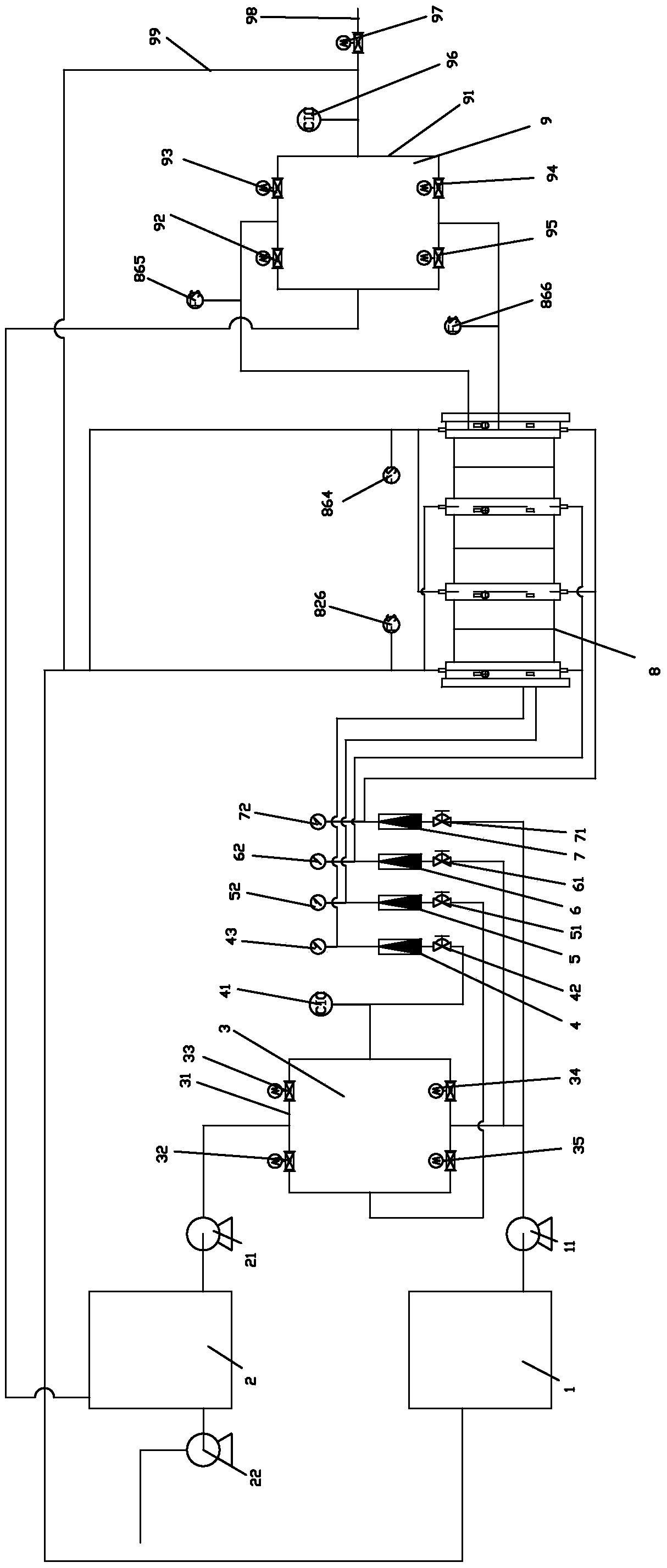
[0083] Such as Figure 1-Figure 4 As shown, an electric-driven membrane desalination unit includes raw water tank 1, concentrated water circulation tank 2, inlet valve group 3, raw water flowmeter 4, concentrated water flowmeter 5, polar water flowmeter I6 and polar water flowmeter II7, Multi-stage membrane stack device 8 and outlet valve group 9,

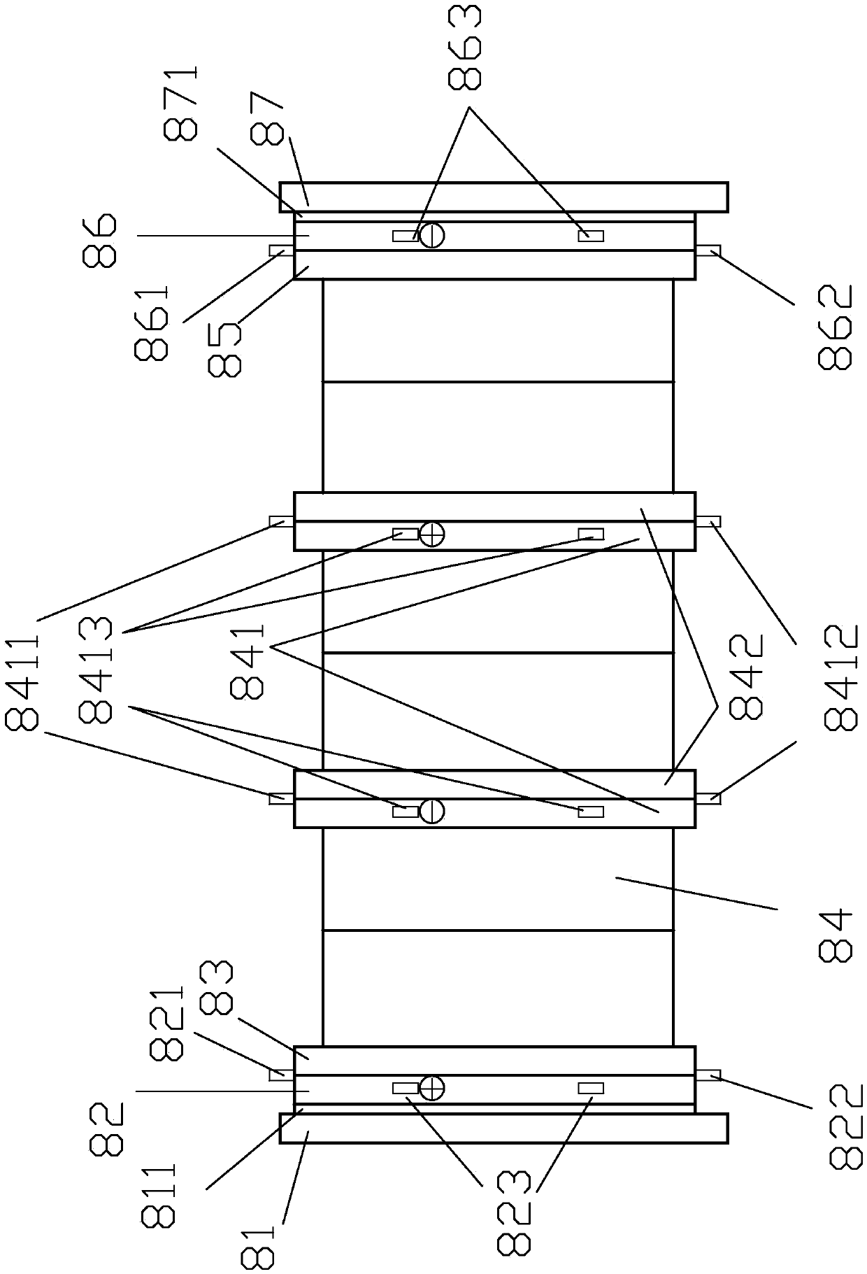
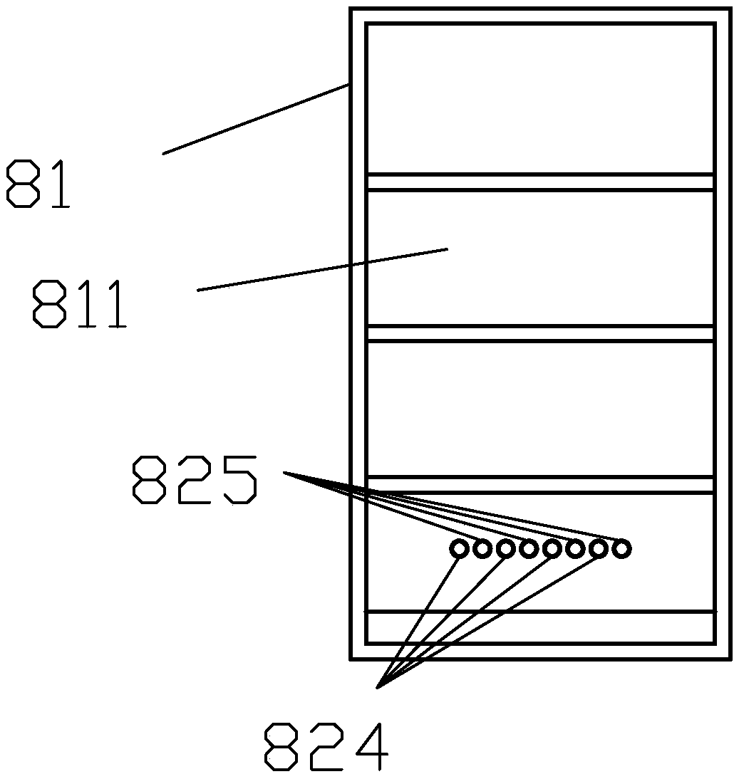
[0084] The multi-stage membrane stack device 8 includes a locking frame I81, a water distribution plate I82, a porous plate I83, a third-stage membrane stack 84, a porous plate II85, a water distribution plate II86, and a locking frame II87 connected in sequence. The membrane stacks of the latter stage are connected sequentially through the common electrode plate 841 and the porous plate III 842,

[0085] A space for accommodating electrodes is provided between the water distribution plate I82 and the perforated plate I83, and the upper part of the connection between the water distribution plate I82 and the perforated plate I83 is...

Embodiment 2

[0117] A water treatment method using the electrically driven membrane desalination unit has the following steps:

[0118] S1. The inlet valve I32 and the inlet valve III34 are opened, the inlet valve II33 and the inlet valve IV35 are closed, the outlet valve I92 and the outlet valve III94 are opened, the outlet valve II93 and the outlet valve The valve IV 95 is closed, the water production valve 97 is closed, and after the preset time I is reached, the two adjacent electrodes are respectively connected to the positive pole and the negative pole of the power supply,

[0119] The raw water enters the multi-stage membrane stack device 8 through the raw water pump 11, the inlet valve III34, the raw water detection unit 41, the diaphragm valve I42, the raw water flowmeter 4 and the electric contact pressure gauge I43 process to obtain produced water, and the produced water passes through the outlet water flow switch II 866 and the outlet valve III 94 to the produced water detectio...


PUM


Abstract

The invention discloses an electrically-driven membrane desalting unit. The electrically-driven membrane desalting unit comprises a raw water tank, a concentrated water circulation tank, an inlet valve set, a raw water flow meter, a concentrated water flow meter, an electrode water flow meter I, an electrode water flow meter II, a multi-stage membrane stacking device and an outlet valve set. The invention further discloses a water treatment method using the unit. According to the electrically-driven membrane desalting unit and the water treatment method using the same, the electrode reversing process is more accurate and reliable; an electro connecting pressure gauge is arranged, and thus a protection effect on whole equipment is achieved; a stainless steel plate is additionally arranged, and thus a pvc plate is effectively prevented from being scratched or collided; the plastic welding technology is adopted, so that the probability of water leakage of a space for containing electrodes is greatly reduced, and water leakage maintenance is quicker; the inlet and outlet directions of electrode water are identical with the flowing directions of the electrode water in the equipment, and thus gas and dirt in the space for containing the electrodes can be discharged out more easily; a sunlight plate is additionally installed on the side face of a membrane pile, and thus a protection effect on the membrane pile is achieved; a water flow switch is additionally arranged at the water outlet end, and the membrane burning phenomenon is effectively prevented; the unit is small in occupied area, more compact integrally, attractive and elegant.

Description

technical field [0001] The invention relates to the field of water treatment, in particular to an electrically driven membrane desalination unit and a water treatment method using the unit. Background technique [0002] Electrodialysis, referred to as ED method, uses anion and cation exchange membranes alternately arranged between the positive and negative electrodes, and separates them with a special separator to form two systems of desalination, desalination and concentration. When brine is passed into the compartment, under the action of a DC electric field, the cations migrate to the negative electrode and can only pass through the cation exchange membrane, while the anions migrate to the positive electrode and can only pass through the anion exchange membrane, so that the brine in the dilute chamber is desalinated. The brine in the concentrated chamber is concentrated. However, during operation, due to the alkaline nature of the cathode and the concentration chamber, f...

Claims


Application Information

Patent Timeline
IPC IPC(8): C02F1/469
CPCY02W10/37C02F1/4695C02F1/46104C02F2209/005
Inventor 韩国美孙杰
Owner DALIAN JIARUI ENVIRONMENTAL PROTECTION SCI & TECH
Why Eureka
Try Eureka