Wireless equipment test system
A test system and wireless device technology, applied in the field of communication, can solve the problems of increasing the construction cost of the darkroom, increasing the measurement interference of the mechanical support structure, increasing the complexity of the system, etc., and achieving the effect of good measurement accuracy
- Summary
- Abstract
- Description
- Claims
- Application Information
AI Technical Summary
Problems solved by technology
Method used
Image

Examples
Embodiment Construction
[0025] Embodiments of the present invention will be described in detail below. It should be emphasized that the following description is only exemplary and not intended to limit the scope of the invention and its application.
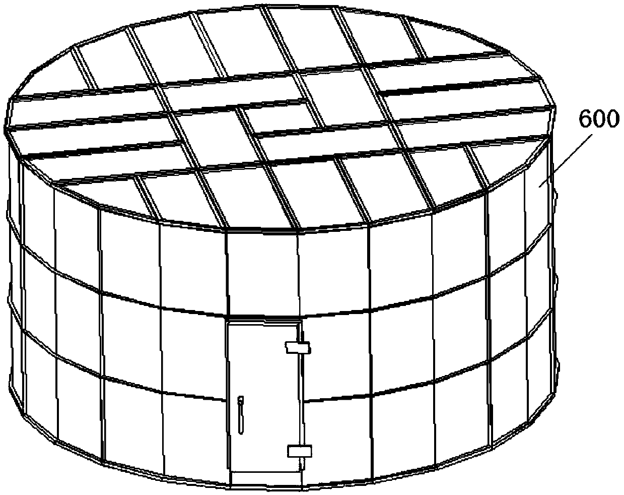
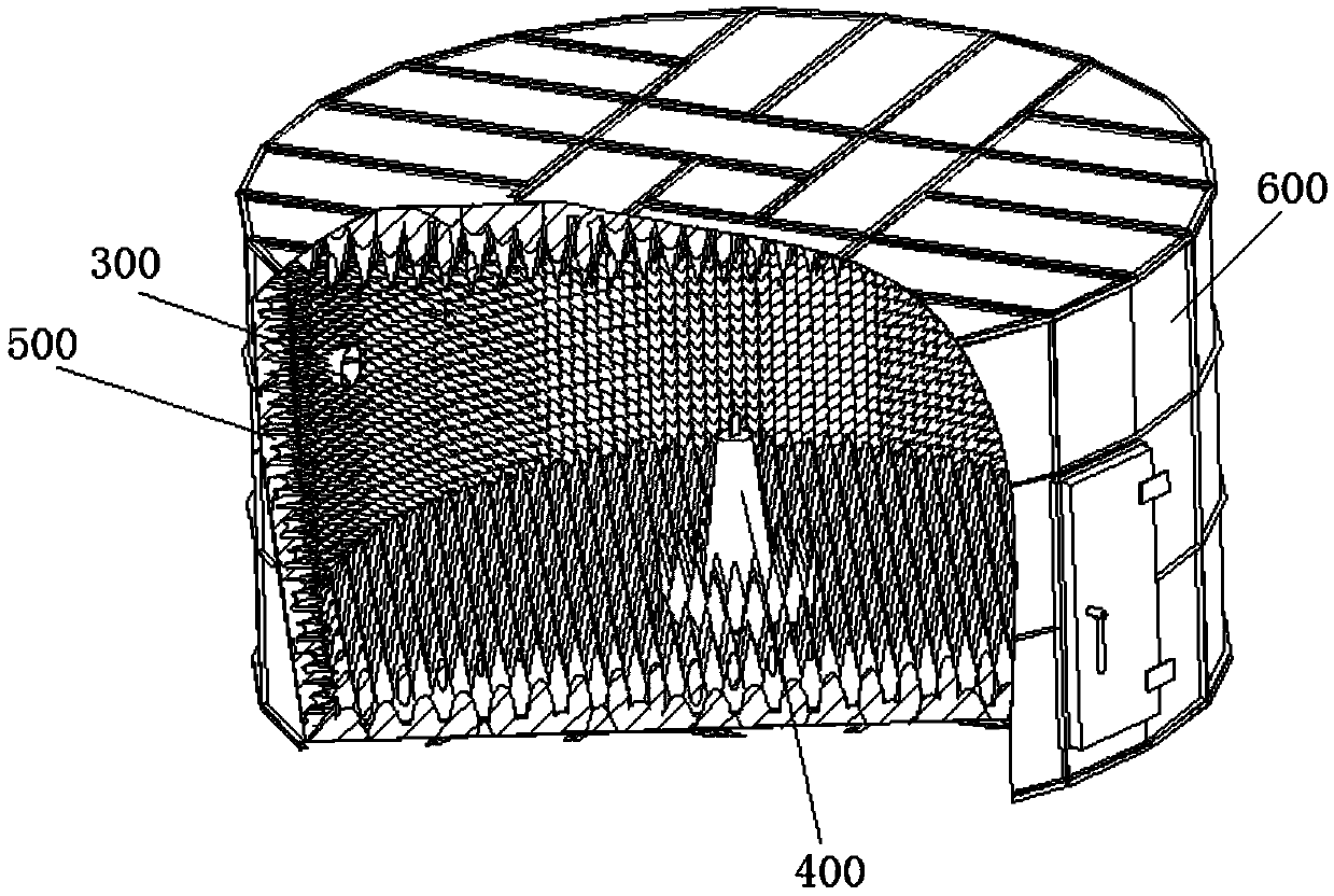
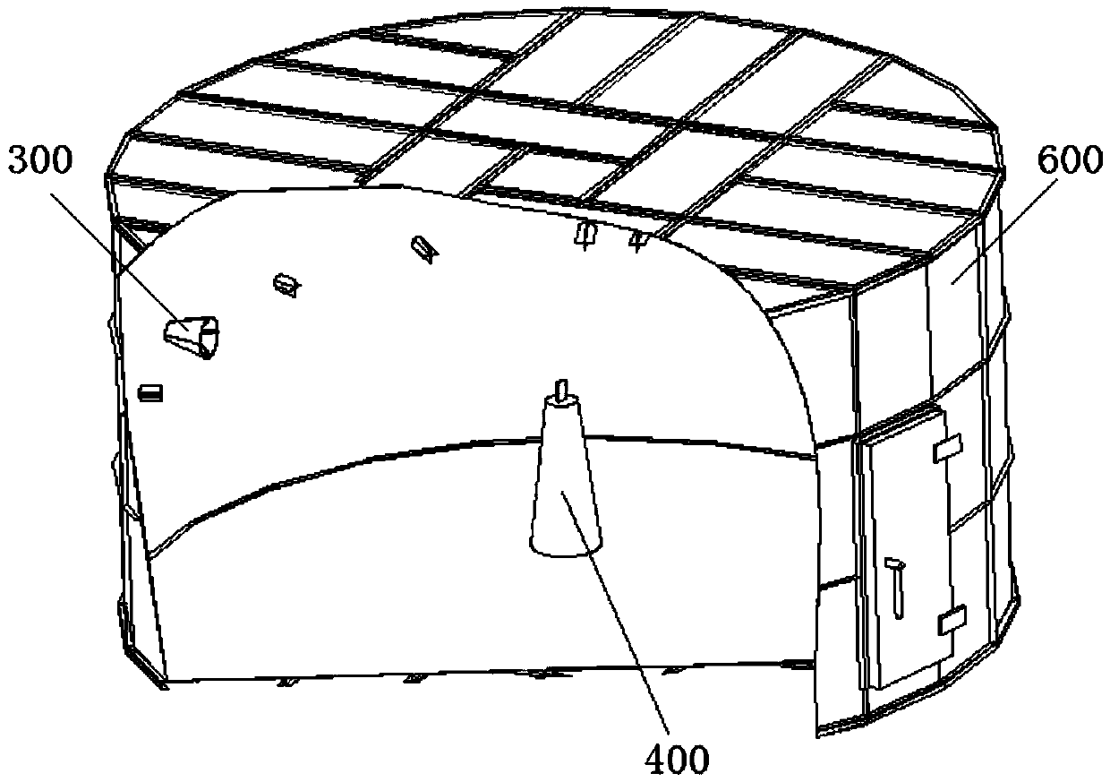
[0026] refer to Figure 1 to Figure 4 , in one embodiment, a wireless device testing system, including a shielding case 600 forming a dark room, a test antenna 300 installed on the inner wall of the shielding case 600, and a test turntable 400 located in the center of the shielding case 600 . The test turntable 400 is used to place wireless devices to be tested, such as mobile phones and other wireless terminals. The test antenna 300 includes 8 multiplexed dual-polarized probe antennas 301-308 arranged around the inner wall of the shielding case 600 in a circular shape at intervals of 45°, and 8 multiplexed dual-polarized probe antennas 301-308 Arrange along the same circular ring (the circular ring in this embodiment refers to the virtual circular r...
PUM
 Abstract
Description
Claims
Application Information
 - Generate Ideas
- Intellectual Property
- Life Sciences
- Materials
- Tech Scout
- Unparalleled Data Quality
- Higher Quality Content
- 60% Fewer Hallucinations
Browse by: Latest US Patents, China's latest patents, Technical Efficacy Thesaurus, Application Domain, Technology Topic, Popular Technical Reports.
© 2025 PatSnap. All rights reserved.Legal|Privacy policy|Modern Slavery Act Transparency Statement|Sitemap|About US| Contact US: help@patsnap.com