Hard-alloy turning tool
A technology of cemented carbide and turning tools, which is applied in the direction of tools for lathes, turning equipment, cutting blades, etc., can solve the problem of insufficient machining accuracy of carbide turning tools, and achieve the goal of eliminating installation errors and uniform changes in turning stress Effect
- Summary
- Abstract
- Description
- Claims
- Application Information
AI Technical Summary
Problems solved by technology
Method used
Image

Examples
Embodiment Construction
[0011] Embodiments of the present invention are described in further detail below in conjunction with the accompanying drawings:
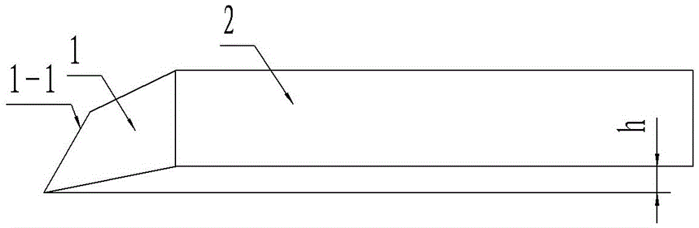
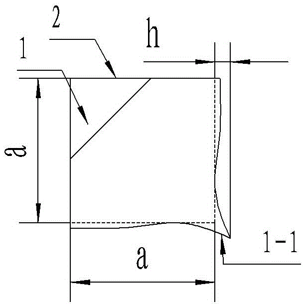
[0012] Such as figure 1 , figure 2 The shown cemented carbide turning tool includes a tool bar 2 and a tool head 1 connected to one end of the tool bar 2, and the tool bar 2 and the tool head 1 are integrally formed. Therefore, the formation of installation errors is completely eliminated, and the error impact of the tool on the processed parts is reduced to the minimum.
[0013] The cross-section of the knife rod part 2 is a square, and the width of each side is a. The cutter head 1 is inclined to an included angle of the cross-section of the cutter bar part 2, and the cutting edge section 1-1 of the cutter head part 1 is formed at the most pointed point, and the most pointed part of the cutting edge section 1-1 protrudes from the cutter bar part The side surface of the cutting edge section 1-1 is inclined to a circular arc concave between the...
PUM
 Abstract
Description
Claims
Application Information
 - Generate Ideas
- Intellectual Property
- Life Sciences
- Materials
- Tech Scout
- Unparalleled Data Quality
- Higher Quality Content
- 60% Fewer Hallucinations
Browse by: Latest US Patents, China's latest patents, Technical Efficacy Thesaurus, Application Domain, Technology Topic, Popular Technical Reports.
© 2025 PatSnap. All rights reserved.Legal|Privacy policy|Modern Slavery Act Transparency Statement|Sitemap|About US| Contact US: help@patsnap.com