Check patentability & draft patents in minutes with Patsnap Eureka AI!

Method and apparatus for profile and surface preparation of retaining rings for use in chemical mechanical polishing processes

A technology for retaining rings and outer rings, applied in the field of polishing systems, which can solve problems such as high capital and labor costs, and poor efficiency

Active Publication Date: 2020-01-07
APPLIED MATERIALS INC
View PDF9 Cites 6 Cited by
  • Summary
  • Abstract
  • Description
  • Claims
  • Application Information

AI Technical Summary

Problems solved by technology

However, this method is inefficient due to high capital and labor costs

Method used


Image

  • Method and apparatus for profile and surface preparation of retaining rings for use in chemical mechanical polishing processes
  • Method and apparatus for profile and surface preparation of retaining rings for use in chemical mechanical polishing processes
  • Method and apparatus for profile and surface preparation of retaining rings for use in chemical mechanical polishing processes

Examples


Embodiment Construction

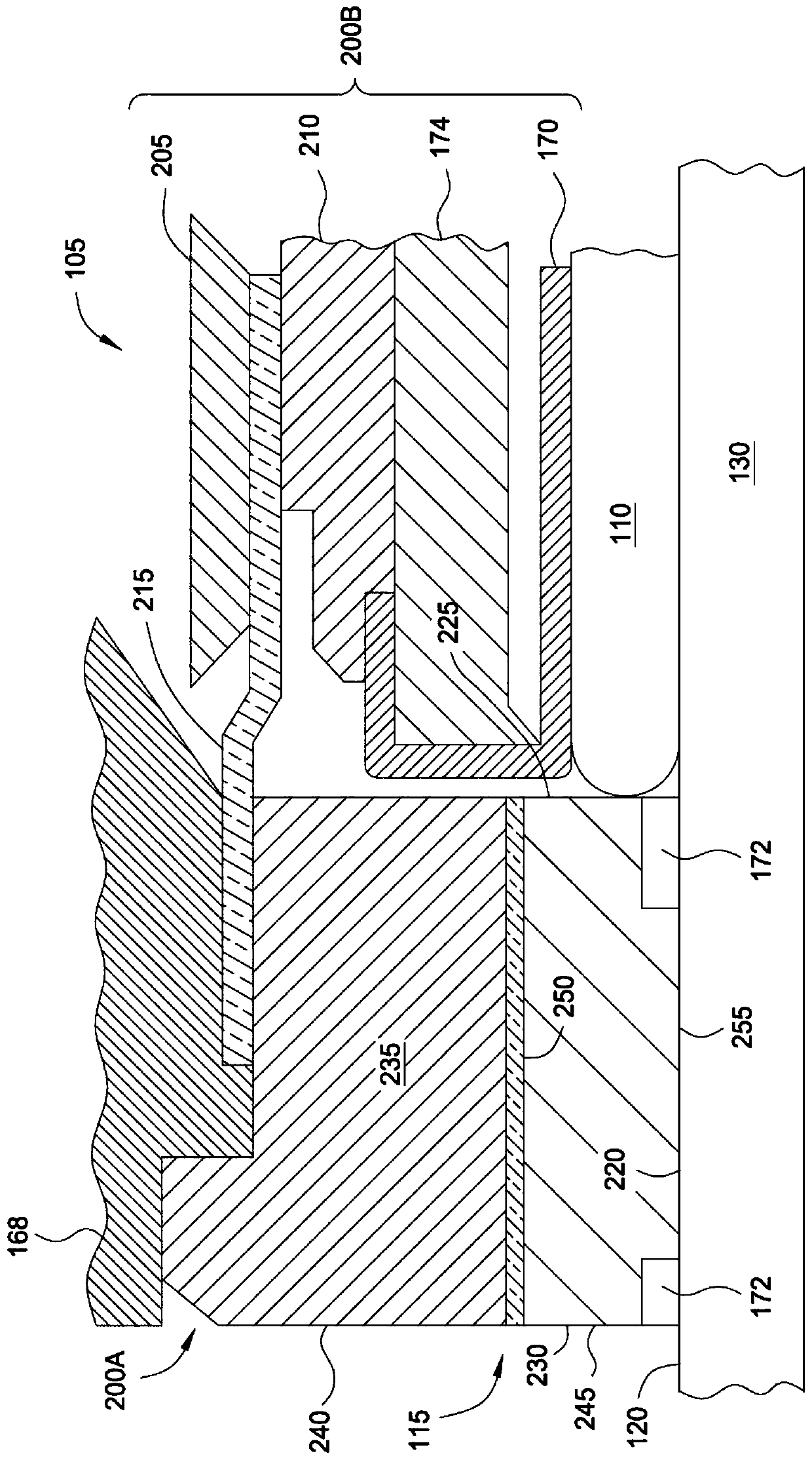
[0026] Retaining rings for polishing substrates, and methods for conditioning and / or refurbishing retaining rings are described herein. An apparatus for carrying out the method includes a fixture assembly coupled to a retaining ring to facilitate dressing and / or refurbishing.

[0027] figure 1 is a partial cross-sectional view of a chemical mechanical polishing (CMP) system 100 . The CMP system 100 includes a carrier head 105 that holds a substrate 110 (shown in phantom) in a retaining ring 115 and places the substrate 110 in contact with a polishing surface 120 of a polishing pad 125 during processing. The polishing pad 125 is disposed on the platen 130 . The platen 130 may be coupled to the motor 132 via a platen shaft 134 . Motor 132 rotates platen 130 , and thus polishing surface 120 of polishing pad 125 , about axis 136 of platen shaft 134 while CMP system 100 is polishing substrate 110 .

[0028] CMP system 100 may include chemical delivery system 138 and pad cleani...


PUM


Abstract

A fixture for forming a sacrificial surface on a retaining ring comprising: a fixture plate sized to substantially match the outer diameter of the retaining ring; and clamping means adapted to provide A side load is applied to one of the inner diameter sidewall or the outer diameter sidewall of the lower portion of the retaining ring.

Description

technical field [0001] Embodiments of the present disclosure relate to polishing systems for polishing substrates, such as semiconductor substrates. More specifically, embodiments relate to retaining rings useful in chemical mechanical planarization (CMP) systems. Background technique [0002] Chemical mechanical polishing (CMP) is a process commonly used in the manufacture of high density integrated circuits to planarize or polish layers of material deposited on a substrate. The carrier head may provide the substrate held therein to a polishing station of the CMP system and controllably push the substrate against the moving polishing pad. CMP is effectively utilized by providing contact between feature sides of the substrate and moving the substrate relative to the polishing pad in the presence of a polishing fluid. Material is removed from the feature side of the substrate in contact with the polishing surface by a combination of chemical and mechanical activity. Partic...

Claims


Application Information

Patent Timeline
Patent Type & Authority Patents(China)
IPC IPC(8): B24B37/32
CPCB24B37/32B24B37/105B24B57/02
Inventor 大卫·理之·石川吴正勋加勒特·何·易·施查尔斯·C·加勒森张焕波裴嘉定尼拉吉·普拉萨德朱利奥·大卫·穆斯基斯
Owner APPLIED MATERIALS INC
Features
  • R&D
  • Intellectual Property
  • Life Sciences
  • Materials
  • Tech Scout
  • Unparalleled Data Quality
  • Higher Quality Content
  • 60% Fewer Hallucinations
Learn More