Contact state switching device and method with fast response
A state-switching, fast-response technology, applied in the direction of high-voltage air circuit breakers, electrical components, electric switches, etc., can solve problems such as no description or report found, no data collected, etc., and achieve the effect of circuit breaker
- Summary
- Abstract
- Description
- Claims
- Application Information
AI Technical Summary
Problems solved by technology
Method used
Image

Examples
no. 1 example
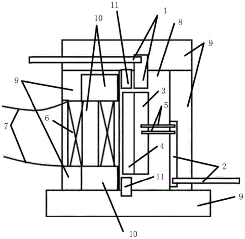
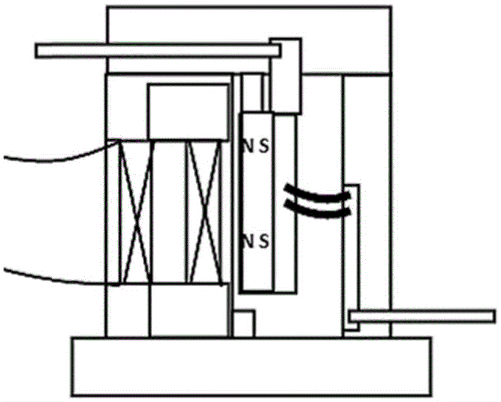
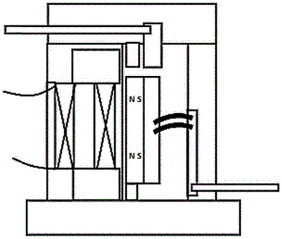
[0090] The first embodiment is a preferred example of the basic embodiment. In the first embodiment, the working principle is: under the excitation of the electromagnetic excitation mechanism, the magnetic force acts on the permanent magnet or ferromagnet formed by the magnetic pole arrangement and the desired movement direction which are easier to realize the movement effect through the yoke and the ferromagnet, The moving magnet is driven to translate along the up and down direction of the paper, thereby driving the moving conductor to translate together. Such as figure 2 As shown, the moving conductor contacts the first electrode, so that an electrical connection is formed between the first electrode, the moving conductor and the second electrode. Such as image 3 As shown, the moving conductor is separated from the first electrode, so that the electrical connection between the first electrode and the second electrode is broken. During the translation process of the mov...
no. 2 example
[0092] The second embodiment is a preferred example of the basic embodiment and also a variation example of the first embodiment. In the second embodiment, the working principle is: the moving magnet translates along the left and right directions of the paper. The dotted line therein represents the deformation state of the conductive elastic body when the moving conductor is in contact with the first electrode. Wherein, the number of moving magnets made of permanent magnets is two, and these two moving magnets are arranged and connected on the same moving conductor in a manner that their magnetic axes are in the same direction and parallel (preferably coincident), and these two moving magnets are located at Both sides of the magnetic axis of the electromagnet in the coil of the electromagnetic excitation mechanism, and. When the electromagnetic excitation mechanism is not activated, due to the supporting effect of the conductive elastic body, the movable conductor is separate...
no. 3 example
[0094] The third embodiment is a preferred example of the basic embodiment, and is also a variation example of the first embodiment or the second embodiment. In the third embodiment, the working principle is: the moving magnet translates along the left and right directions of the paper. The dotted line therein represents the deformation state of the conductive elastic body when the moving conductor is in contact with the first electrode. A rolling guide part is arranged between the moving magnet and the cavity wall of the vacuum chamber below the moving magnet, so that the required magnetic force for driving the moving magnet is reduced, thereby facilitating fast driving. Wherein, the rolling guide component may be a ball or a slide rail, so as to achieve the effect of reducing movement resistance. Wherein, since the two electromagnetic excitation coils in the electromagnetic excitation mechanism are respectively located on both sides of the moving magnet, the moving magnet c...
PUM
 Abstract
Description
Claims
Application Information
 - R&D
- Intellectual Property
- Life Sciences
- Materials
- Tech Scout
- Unparalleled Data Quality
- Higher Quality Content
- 60% Fewer Hallucinations
Browse by: Latest US Patents, China's latest patents, Technical Efficacy Thesaurus, Application Domain, Technology Topic, Popular Technical Reports.
© 2025 PatSnap. All rights reserved.Legal|Privacy policy|Modern Slavery Act Transparency Statement|Sitemap|About US| Contact US: help@patsnap.com