Unified communications module (UCM)

A communication interface, system integration technology, applied in transmission systems, general control systems, control/regulation systems, etc., can solve problems such as not yet succeeded, and achieve the effect of preventing changes

Active Publication Date: 2016-05-25
SCHNEIDER ELECTRIC SYST USA INC
View PDF5 Cites 0 Cited by
  • Summary
  • Abstract
  • Description
  • Claims
  • Application Information

AI Technical Summary

Problems solved by technology

Various improvements related to minimizing the number of hardware components required to implement a fault-tolerant controller a

Method used


Image

  • Unified communications module (UCM)
  • Unified communications module (UCM)
  • Unified communications module (UCM)

Examples


Example Embodiment

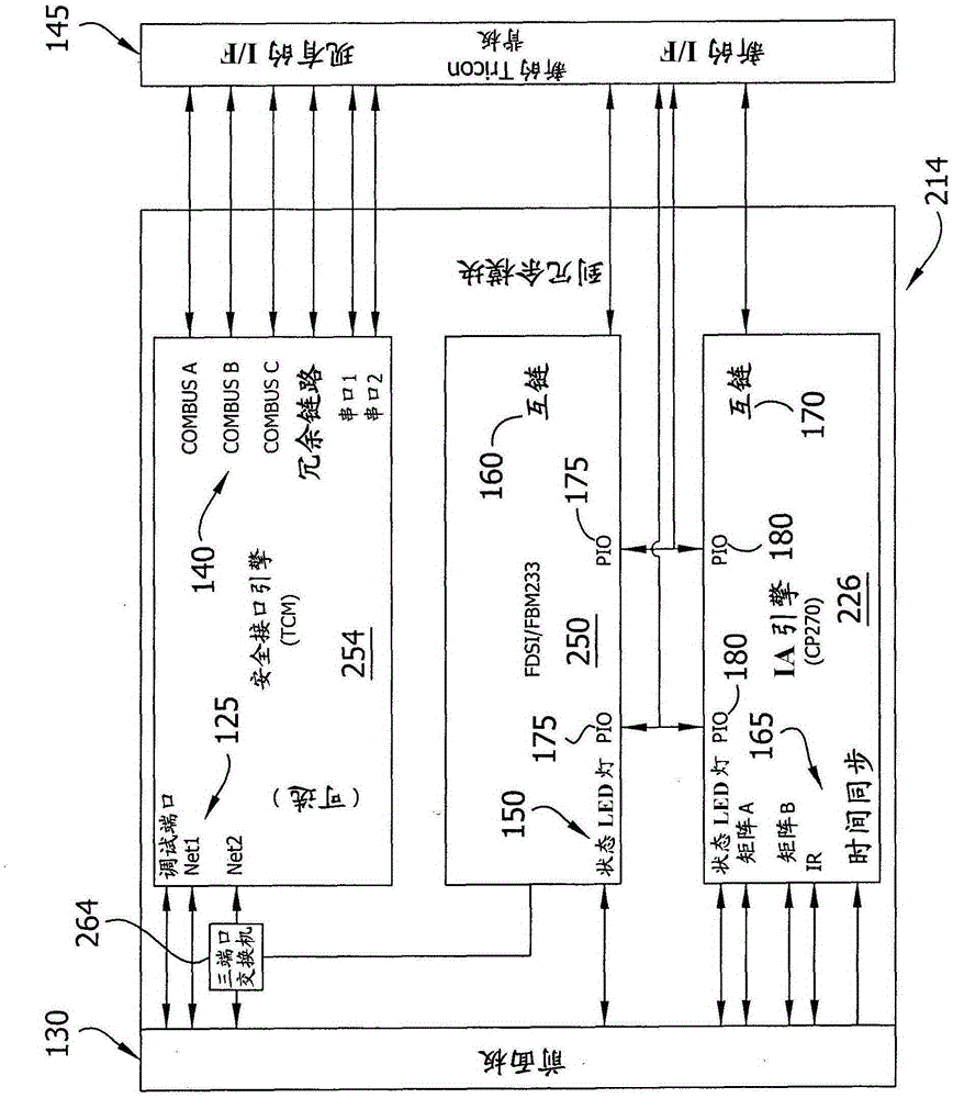
[0019] Aspects of the present invention relate to hardware and software components for use in a distributed process control environment, and more specifically, to the integration of the functions of hardware and software related to process control. The UCM implementing aspects of the present invention includes a semi-fault-tolerant, three-in-one interface (3-to-1 interface) between its communication port and the main processor (MP) of the fault-tolerant controller.

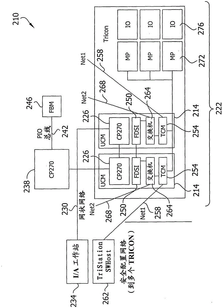
[0020] Go to figure 1 , At 210 generally indicates a fault-tolerant controller implementing aspects of the present invention. The UCM 214 is shown in the case 222 of the fault-tolerant controller 210 as seen. In one embodiment, the fault-tolerant controller 210 includes multiple UCMs 214 that operate independently and can provide true control network redundancy, which will be described further below. Three separate modules are shown in UCM214, which provide physical and functional separation of at least two differen...


PUM


Abstract

A fault tolerant control system delivers an embedded functional safety core and a distributed control engine with an onboard communication link in an industrial process control environment. The fault tolerant control system includes a process control workstation connected to a first network and a fault tolerant safety controller connected to a second network, wherein a process controller module, a safety controller module and a field device system integration module are co-located on a power interface board.

Description

Technical field [0001] In process control systems, such as distributed control systems (DCS), fault tolerance enables continued operation in the event of component failure within the system or in the event that the system suffers from transient errors from various sources. One aspect common to fault-tolerant systems involves the concept of redundancy, which can be simply defined as backup components that become operable when a failure occurs, thereby allowing the system to continue operating as expected. Safety instrumented systems (SIS) are known in the art, which are used to continuously operate in a "safe state" by using a fault-tolerant controller to avoid adverse safety and health consequences. Such fault-tolerant controllers are generally used in hazard protection systems (ie, systems that regulate the operation of nuclear power plants, turbines, fire and gas sensing systems, etc.). Background technique [0002] The control components of known fault-tolerant controllers us...

Claims


Application Information

Patent Timeline
IPC IPC(8): G05B9/03H04L45/28
CPCG05B9/00G05B19/41855G05B2219/31245G05B2219/33273Y02P90/02G06F11/2007H04L45/28
Inventor J·C·卡布勒M·乔P·P·克拉尔A·P·米什拉
Owner SCHNEIDER ELECTRIC SYST USA INC
Why Eureka
Try Eureka