Supercharge Your Innovation With Domain-Expert AI Agents!

Pipeline double-row deformation detection mechanism

A detection mechanism, double-row technology, applied in the direction of measuring devices, instruments, etc., to achieve the effect of avoiding missed detection, improving the ability to overcome obstacles, and improving accuracy

Inactive Publication Date: 2016-06-15
CHINA PETROCHEMICAL CORP +1
View PDF7 Cites 11 Cited by
  • Summary
  • Abstract
  • Description
  • Claims
  • Application Information

AI Technical Summary

Benefits of technology

This technology helps prevent damage or malfunctions caused by pipelines that may have changed over time due to factors like temperature changes (thermal expansion) or pressure differences between different parts of the pipe system. By monitoring these issues with multiple sensors placed at specific locations around the circumference of each part of the structure being monitored, this innovation allows for more efficient use of resources while maintaining safety standards.

Problems solved by technology

This patented technical problem addressed during developing an effective method for detecting flaws (such as cracks) along a pipeline' s inner surface is finding any signs of damage caused due to environmental conditions like temperature variations overshootings, pressure differences between different parts of the system, etc., which could lead to leaks when they occur. Current methods require manual inspections with tools called guided missile guns equipped with sensors, but these are often limited because they only work at specific points within the pipeline.

Method used


Image

  • Pipeline double-row deformation detection mechanism
  • Pipeline double-row deformation detection mechanism

Examples


Embodiment Construction

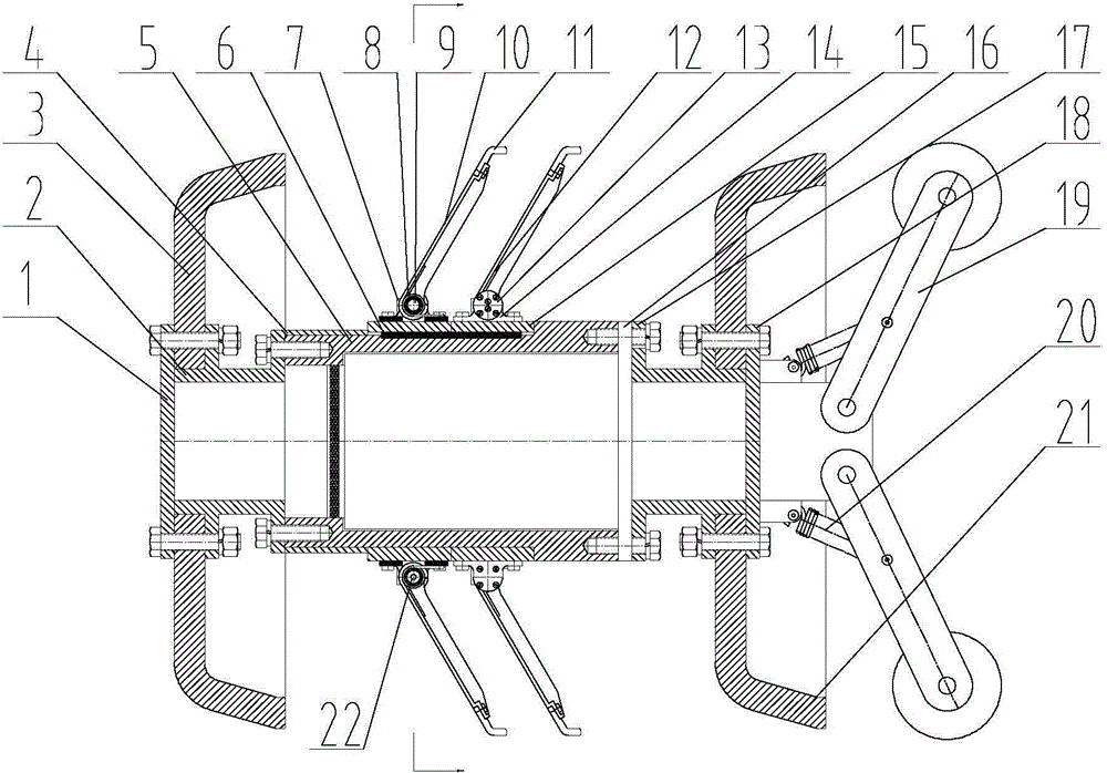
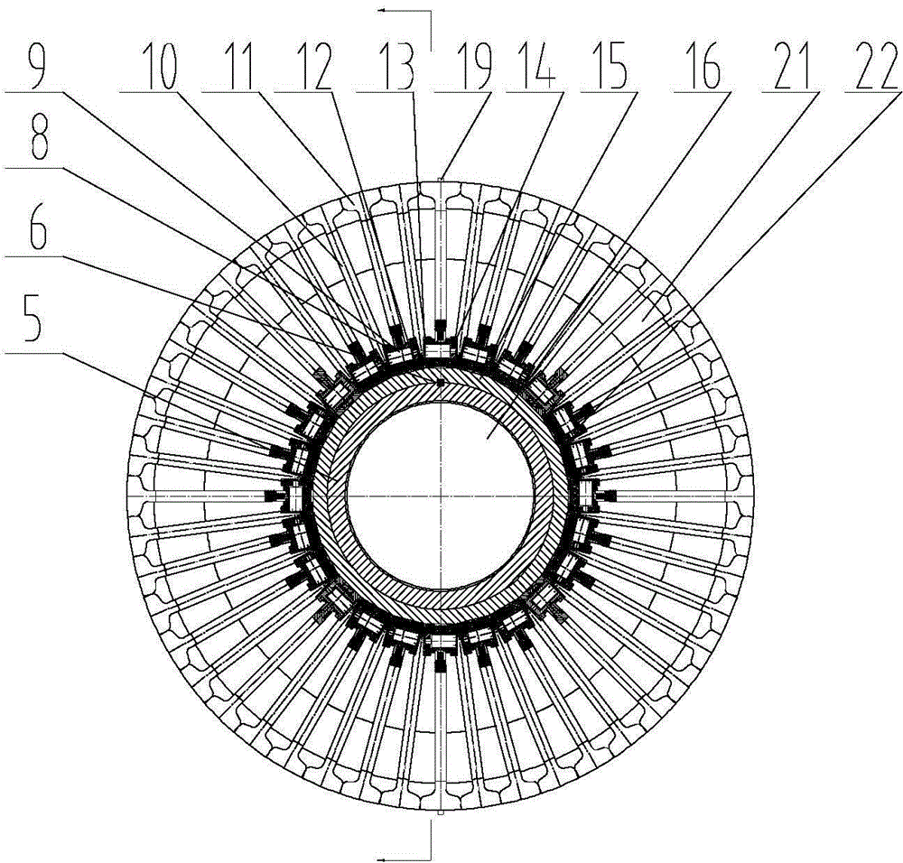
[0020] Attached to the manual figure 1 , 2 , Further describe the present invention:

[0021] Pipeline double -row deformed detection mechanism from front end cover 1. Ahead of the front holder 2, front leather bowl 3, fixed set 4, cylinder 5, positioning key 6, limit block 7, sales axis 8, angle displacement sensor 9, sensing arm arm 10. Sensor 11, twisted spring 12, end cover 13, supporting seat 14, sliding ring 15, sealing cabin 16, rear bracket 17, back end cover 18, mileage meter 19, pull spring 20, rear skin bowl 21, 21, rear skin bowl 21, 21, rear skin bowl 21, 21, 21, rear skin bowl 21, 21, 21, rear skin bowl 21, 21, 21, rear skin bowl 21, 21, 21, rear skin bowl 21, 21, 21, rear skin bowl 21. Sensing block 22 composition. The front end of the cylinder 5 is connected to the front bracket 2 through the screw connection, and the back end of the cylinder 5 is connected to the screw cabin 16 and the rear bracket 17, and the front leather bowl 3 is fixed on the front brack...


PUM


Abstract

The invention relates to a pipeline double-row deformation detection mechanism. A front leather cup and a rear leather cup are connected to the front and rear ends of a cylinder through a front bracket and a rear bracket respectively. Two rows of sensing arms, with one row behind the other, are arranged outside the cylinder. Each row of sensing arms is composed of multiple independent sensing arms circumferentially distributed at equal intervals. The two rows of sensing arms are alternately distributed back and forth. Each sensing arm is hinged to a pin shaft through a support connected to the cylinder. The outer end of each sensing arm is equipped with a sensing body. The supports and the sensing arms are connected by torsion springs and form sensing arm expansion fit. An angular displacement sensor and a sensing block are arranged at the joint of each sensing arm and the corresponding support. A speedometer is arranged on the cylinder or on the brackets. A sealed cabin is arranged inside the cylinder. The mechanism has the characteristics of high detection resolution, compact structure, high reliability, fast response of the sensing bodies, high detection accuracy, strong ability of obstacle crossing inside a pipeline, convenient maintenance, and the like.

Description


Claims


Application Information

Patent Timeline
Owner CHINA PETROCHEMICAL CORP
Features
  • R&D
  • Intellectual Property
  • Life Sciences
  • Materials
  • Tech Scout
  • Unparalleled Data Quality
  • Higher Quality Content
  • 60% Fewer Hallucinations
Learn More