Magnetic power stirring machine

A technology of magnetic power and mixer, which is applied in home appliances, applications, kitchen utensils, etc., can solve the problems of unstable high-speed operation, low efficiency, and loud noise, and achieve the effect of simple structure, not easy to dump, and stable operation

Inactive Publication Date: 2016-07-13
ZHONGSHAN CITY GOLDLABO ELECTRIC CO LTD
View PDF6 Cites 13 Cited by
  • Summary
  • Abstract
  • Description
  • Claims
  • Application Information

AI Technical Summary

Problems solved by technology

[0006] The purpose of the present invention is to provide a magnetic power mixer, whi

Method used


Image

  • Magnetic power stirring machine
  • Magnetic power stirring machine
  • Magnetic power stirring machine

Examples


Embodiment 1

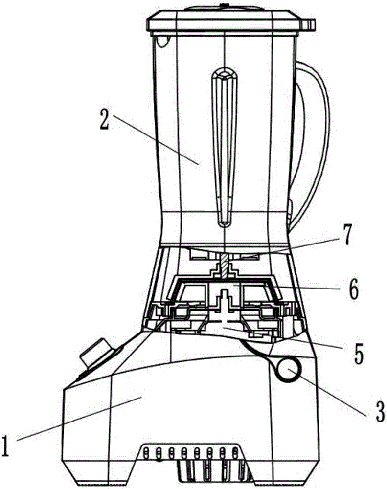
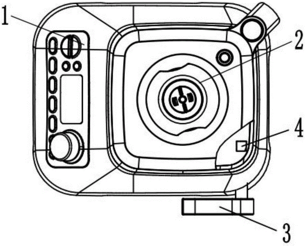
[0042] Refer below Figure 1 to Figure 7 To further explain this application, such as figure 1 , figure 2 and image 3 A kind of magnetic power mixer shown, comprises base 1, stirring cup 2, magnetic power mechanism 6 and motor 5, described base 1 is provided with control panel 11, is used for controlling the running state of motor, and described stirring cup 2 is fixed It is arranged on the base 1 , the magnetic power mechanism 6 is located between the bases 1 , and the motor 5 is connected with the magnetic power mechanism 6 . The base 1, the stirring cup 2, the magnetic power mechanism 6 and the motor 5 are coaxially arranged.

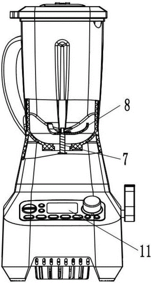
[0043] Such as figure 2 As shown, the stirring cup 2 also includes a driven power shaft 7 and several blades 8, one end of the driven power shaft 7 is provided with several blades 8, and the blades 8 are located in the stirring cup 2 .

[0044] Preferably, the number of said blades 8 is six.

[0045] Such as image 3 As shown, the magnetic...

Embodiment 2

[0052] Refer below Figure 4 to Figure 11 To further explain this application, such as Figure 8 and Figure 9 A kind of magnetic power mixer shown, comprises base 1, stirring cup 2, magnetic power mechanism 6 and motor 5, described base 1 is provided with control panel 11, is used for controlling the running state of motor, and described stirring cup 2 is fixed Set on the base 1, the magnetic power mechanism 6 is located in the base 1, the motor 5 is connected with the magnetic power mechanism 6, wherein the stirring cup 2 includes a driven power shaft 7 and A plurality of blades 8, one end of the driven power shaft 7 is provided with a plurality of blades 8, and the blades 8 are located in the stirring cup 2.

[0053] Preferably, the number of the blades 8 is 1-6.

[0054] Optimally, the number of said blades 8 is three.

[0055] Such as Figure 9 As shown, the magnetic power mixer also includes a push pin 3 and a push rod 4, the push rod 4 is movably arranged on the si...


PUM


Abstract

The invention provides a magnetic power stirring machine. The magnetic power stirring machine comprises a base, a stirring cup and a magnetic powder mechanism, wherein the magnetic power mechanism comprises a driving magnet combination and a driven magnet combination; the driving magnet combination is arranged on the base; the driven magnet combination is arranged at the bottom of the stirring cup, wherein the base is movably connected with the stirring cup through a concave-convex stage; a gap is reserved between the base and the stirring cup; the driving magnet combination and the driven magnet combination are parallel to each other and are arranged at a certain angle; circumferential attraction force exists between the driving magnet combination and the driven magnet combination. According to the magnetic power stirring machine provided by the invention, a driven power magnetic pole is arranged on the driving magnet combination in a sleeving manner, and N magnetic poles and S magnetic poles of the driven power magnetic pole and the driving magnet combination are arranged at intervals; magnets are arranged at a certain angle; the magnetic power stirring machine is easy to carry out alignment, is labour-saving and convenient when the magnetic power stirring machine is taken and placed and is uniform in stress, and can operate at a high speed; the gravity centre can be lowered because a transmission mechanism is arranged, so that the operation is smooth and stable.

Description

technical field [0001] The invention relates to a small household appliance for daily use, in particular to a magnetic power mixer. Background technique [0002] The traditional cooking mixer mainly includes a cup base and a mixing cup. The seal between the mixing cup and the cup base mostly relies on threaded connection or directly fixes the mixing cup and the cup base together. Most of the existing food cooking mixers also use The motor drive device is installed in the head cover or on the base, and drives the blade or stirring device to work through gear meshing. Such a mechanism is easy to clean and inconvenient to use, and it is noisy and complicated to install. [0003] However, the above-mentioned disassembly method is very inconvenient, not conducive to disassembly and cleaning operations, and takes up a lot of time for the user; it is noisy during use, and cannot be used for a long time due to the large heat generated during use, so there is a magnetic force. blend...

Claims


Application Information

Patent Timeline
IPC IPC(8): A47J43/046A47J43/08
CPCA47J43/0465A47J43/085
Inventor 王文
Owner ZHONGSHAN CITY GOLDLABO ELECTRIC CO LTD
Why Eureka
Try Eureka