Supercharge Your Innovation With Domain-Expert AI Agents!

A method and auxiliary device for manufacturing a heat exchange tube exposed heat exchanger

A technology of auxiliary devices and heat exchange tubes, applied in auxiliary devices, manufacturing tools, auxiliary welding equipment, etc., can solve problems such as large flexibility, heat exchange tube damage, and long tube bundle length, so as to facilitate mass production and improve the degree of automation , the effect of improving work efficiency

Active Publication Date: 2018-01-12
HARBIN ELECTRIC CORP QINHUANGDAO HEAVY EQUIP
View PDF8 Cites 0 Cited by
  • Summary
  • Abstract
  • Description
  • Claims
  • Application Information

AI Technical Summary

Problems solved by technology

[0002] Since the tube bundle assembly of the heat exchange tube exposed type heat exchanger is long, it is not easy to control the concentricity of the tube holes between the support plates of each tube bundle during assembly; since the heat exchange tube is exposed in the air, its cleaning and protection are not easy to control; After the heat pipe and tube sheet welds are welded, the product requires an air tightness inspection of the welds, but the exposed tube bundle components cannot meet the requirements of sealing the shell side of the tube bundle and inflating the heat exchange tubes and tube sheet welds for air tightness inspection ;Because the heat exchange tubes are exposed and cannot be rotated, the circular seam between the tube sheet and the head needs to be welded in all positions manually, and the welding quality is not easy to guarantee; When hoisting or transferring, due to its special structure, directly binding the heat exchange tubes for hoisting will cause damage to the heat exchange tubes, or the tube bundle assembly is easy to deform due to the long length and flexibility of the tube bundle after lifting

Method used


Image

  • A method and auxiliary device for manufacturing a heat exchange tube exposed heat exchanger
  • A method and auxiliary device for manufacturing a heat exchange tube exposed heat exchanger
  • A method and auxiliary device for manufacturing a heat exchange tube exposed heat exchanger

Examples


Embodiment approach

[0082] According to a preferred embodiment of the present invention, the preparation method also includes:

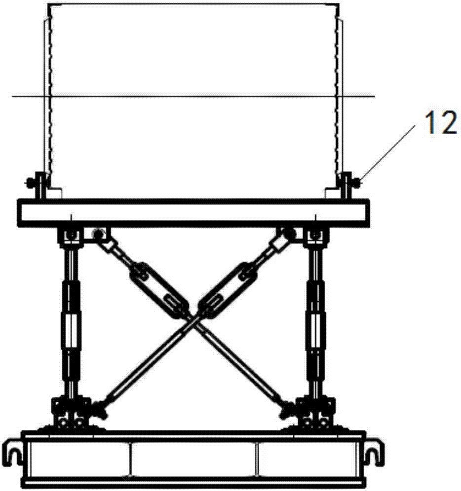
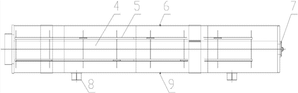
[0083] Step 5): insert the tube bundle assembly 22 after the tube is inserted into the temporary housing device, optionally disassemble the tube sheet support 2 after inserting, and seal and weld the outer edge of the tube sheet 21 with the temporary housing 4, and then optionally Relying on the support 8 to place to the station; and

[0084] Step 6): Sealing the manhole 7 and the air outlet 9, feeding compressed air through the air inlet 6, and checking the airtightness of the weld between the heat exchange tube (or heat exchange tube bundle) and the tube sheet 21 .

[0085] In step 5, the tube bundle assembly after the pipe is inserted into the temporary cylinder 4, the tube bundle assembly slides into the temporary cylinder 4 along the internal support rail 5, and the connecting rod assembly 3 is disassembled at the same time, preferably, during the insertion process...


PUM


Abstract

The invention discloses a method and an auxiliary device for manufacturing a heat exchanger with a heat exchange pipe exposed. The auxiliary device comprises a pipe bundle supporting frame, a temporary shell device and a hoisting device, wherein the pipe bundle supporting frame is used for supporting and assembling a pipe bundle assembly 22, so that all pipe bundle supporting plates of the pipe bundle assembly 22 can be corrected conveniently, and pipe orifices can be aligned conveniently; the temporary shell device realizes automatic welding of a pipe plate 21 and a head girth, thus forming a closed space on the shell side of the pipe bundle assembly to conduct an air tightness test for verifying the weld quality between the heat exchange pipe and the pipe plate; therefore, long-term storage of a heat exchange pipe bundle can be realized, and the cleaning requirement in the process of manufacturing the heat exchanger with the heat exchange pipe exposed is guaranteed; the hoisting device assists in hoisting the pipe bundle assembly.

Description

technical field [0001] The invention relates to the technical field of thermal engineering, in particular to a method and an auxiliary device for manufacturing a flexible heat exchange tube exposed heat exchanger with a long tube bundle assembly and a small tube bundle diameter or cross section. Background technique [0002] Since the tube bundle assembly of the heat exchange tube exposed type heat exchanger is long, it is not easy to control the concentricity of the tube holes between the support plates of each tube bundle during assembly; since the heat exchange tube is exposed in the air, its cleaning and protection are not easy to control; After the heat pipe and tube sheet welds are welded, the product requires an air tightness inspection of the welds, but the exposed tube bundle components cannot meet the requirements of sealing the shell side of the tube bundle and inflating the heat exchange tubes and tube sheet welds for air tightness inspection ;Because the heat ex...

Claims


Application Information

Patent Timeline
Patent Type & Authority Patents(China)
IPC IPC(8): B23K37/04
CPCB23K37/0426B23K2101/14
Inventor 于均刚魏占超欧凡强孟巍冯强黄和国李学鸥杨雪松
Owner HARBIN ELECTRIC CORP QINHUANGDAO HEAVY EQUIP
Features
  • R&D
  • Intellectual Property
  • Life Sciences
  • Materials
  • Tech Scout
  • Unparalleled Data Quality
  • Higher Quality Content
  • 60% Fewer Hallucinations
Learn More