Supercharge Your Innovation With Domain-Expert AI Agents!

Vacuum fast slag tapping system and using method thereof

A technology of fast vacuum and vacuum device, applied in the field of slag discharge system, can solve the problems of long production cycle, easily scratched crystallizer, low production efficiency, etc., and achieve the effect of low cost, small impact and easy cleaning

Pending Publication Date: 2016-07-27
TIANJIN CISRI HARDER MATERIALS & TECH
View PDF4 Cites 0 Cited by
  • Summary
  • Abstract
  • Description
  • Claims
  • Application Information

AI Technical Summary

Problems solved by technology

[0004] Ingot pumping electroslag is an important electroslag method. Ingot pumping electroslag was invented to solve the problem that the length of electroslag ingot is limited by the height of the crystallizer. Using ingot pumping can produce longer electroslag ingots to meet various industrial needs ; However, after the remelting, taking the ingot and cleaning the solid slag in the crystallizer takes a long time in the entire production cycle, about 25%-40%, resulting in low production efficiency; while taking the ingot and cleaning the solid slag in the mold The crux of the long time consumption is that after remelting, it is necessary to wait for the liquid slag on the molten steel to solidify and shrink before pulling out the electroslag ingot. Since the shrinkage rate of the slag is smaller than that of the steel, the solidified slag that solidifies when the electroslag ingot is drawn out often remains in the crystal Therefore, it is necessary to clean the crystallizer separately. For the same reason, when cleaning the crystallizer, it is necessary to wait for the slag to cool and shrink for a long time before cleaning, otherwise cleaning is very difficult, and it is easy to scratch the crystallizer during cleaning.

Method used


Image

  • Vacuum fast slag tapping system and using method thereof

Examples


Embodiment

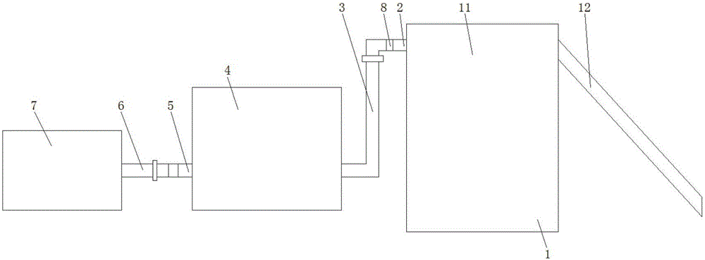
[0020] refer to figure 1 , this embodiment proposes a vacuum rapid slag removal system, including a slag suction tank 1, the slag suction tank 1 includes a slag storage tank 11 and a slag suction pipe 12, the slag suction pipe 12 is located on one side of the slag storage tank 11, and the suction The slag pipe 12 is connected with the air inlet of the slag storage tank 11, and the other side of the slag storage tank 11 is provided with a first air outlet pipe 2, and one end of the first air outlet pipe 2 is connected with the air outlet of the slag storage tank 11, and the first The other end of the air outlet pipe 2 is connected to a metal hose 3 through a connecting device, and the end of the metal hose 3 away from the first air outlet pipe 2 is connected to the air inlet of the intermediate tank 4, which is located on the other side of the slag storage tank 11 , and the gas outlet of the intermediate tank 4 is connected with a second gas outlet pipe 5, the second gas outlet...

example 1

[0024] Example 1: The diameter of the slag suction pipe 12 is 40 mm, the length is 500 mm, the diameter of the slag storage tank 11 is 250 mm, and the height is 320 mm; the angle between the slag suction pipe 12 and the slag storage tank 11 is 45 degrees; When; the diameter of metal hose 3 is 28mm, the diameter of high-pressure hose 6 is 10mm, connect vacuum device 7, intermediate tank 4 and slag suction tank 1, close the air valve 8 in the first air outlet pipe 2, open the second The air valve 8 in the air outlet pipe 5, open the vacuum device 7, and evacuate to -60kpa, the air valve 8 in the second air outlet pipe 5, lift the slag suction pipe 12 with a crane, and insert it into the slag pool that needs slag suction , 25mm away from the metal liquid surface, quickly open the air valve 8 in the first gas outlet pipe 2, all the slag liquid above 25mm away from the metal liquid is sucked into the slag storage tank 11, after the slag suction is completed, the slag suction pipe 12...

example 2

[0025] Example 2: The diameter of the slag suction pipe 12 is 60mm, the length is 420mm, the diameter of the slag storage tank 11 is 380mm, and the height is 480mm; the angle between the slag suction pipe 12 and the slag storage tank 11 is 45 degrees; when the slag suction 20kg The diameter of the metal hose 3 is 30mm, and the diameter of the high-pressure hose 6 is 12mm. Connect the vacuum device 7, the intermediate tank 4 and the slag suction tank 1, close the air valve 8 in the first air outlet pipe 2, and open the second air outlet. The air valve 8 in the air pipe 5, open the vacuum device 7, evacuate to -82kpa, the air valve 8 in the second air outlet pipe 5, use the crane to lift the slag suction pipe 12, insert it into the slag pool that needs slag suction, With a distance of 22mm from the metal liquid surface, quickly open the air valve 8 in the first air outlet pipe 2, and all the slag liquid above 25mm from the metal liquid will be sucked into the slag storage tank 11...


PUM

PropertyMeasurementUnit
diameteraaaaaaaaaa
lengthaaaaaaaaaa
diameteraaaaaaaaaa

Abstract

The invention discloses a vacuum fast slag tapping system and a using method thereof. The vacuum fast slag tapping system comprises a slag absorption tank, wherein the slag absorption tank is composed of a slag storage tank and a slag absorption pipe; the slag absorption pipe is formed in one side of the slag storage tank and is connected with an air inlet of the slag storage tank; a first air outlet pipe is formed in the other side of the slag storage tank; one end of the first air outlet pipe is connected with an air outlet of the slag storage tank; in addition, the other end of the first air outlet pipe is connected with a metal hose through a connecting device; one end, far away from the first air outlet pipe, of the metal hose is connected with an air inlet of a middle tank; the middle tank is arranged on the other side of the slag storage tank; in addition, an air outlet of the middle tank is connected with a second air outlet pipe; the second air outlet pipe is formed in one side, far away from the slag storage tank, of the middle tank; in addition, air valves are formed in the second air outlet pipe and the first air outlet pipe respectively; and one end, far away from the middle tank, of the second air outlet pipe is connected with a high-pressure hose through a connecting device. The vacuum fast slag tapping system has the advantages of simpleness in operation, low cost and convenience in cleaning.

Description

technical field [0001] The invention relates to the technical field of slag discharge system, in particular to a vacuum rapid slag discharge system and its use method. Background technique [0002] With the rapid development of world industry, the manufacturing industry has higher and higher requirements for metallurgical equipment in order to produce higher performance metal materials; since electroslag metallurgy was proposed in the 1940s, because electroslag metallurgy technology has The superiority of the metal, such as the excellent performance of the metal (high purity, fine structure, smooth surface), economical rationality (simple equipment, convenient operation, production cost lower than vacuum arc remelting, high metal yield) and process Stable, flexible and controllable, electroslag metallurgy has developed rapidly in countries all over the world; it has been applied to various fields, including aviation, aerospace, electronics, and atomic energy. [0003] The e...

Claims


Application Information

Patent Timeline
Patent Type & Authority Applications(China)
IPC IPC(8): C22B9/187C22B9/18
CPCC22B9/18
Inventor 王飞
Owner TIANJIN CISRI HARDER MATERIALS & TECH
Features
  • R&D
  • Intellectual Property
  • Life Sciences
  • Materials
  • Tech Scout
  • Unparalleled Data Quality
  • Higher Quality Content
  • 60% Fewer Hallucinations
Learn More