High-efficiency rotor for motor

A high-efficiency, rotor technology, applied in electric components, electrical components, electromechanical devices, etc., can solve problems such as unstable performance and structure, and achieve the effects of high quality and safety stability, stable structure, and convenient installation.

Inactive Publication Date: 2016-07-27
泰信电机(苏州)有限公司
View PDF6 Cites 10 Cited by
  • Summary
  • Abstract
  • Description
  • Claims
  • Application Information

AI Technical Summary

Problems solved by technology

The chips in the common motor rotors are only stacked and piled up. The performance and structure of this kind o

Method used


Image

  • High-efficiency rotor for motor
  • High-efficiency rotor for motor
  • High-efficiency rotor for motor

Examples


Example Embodiment

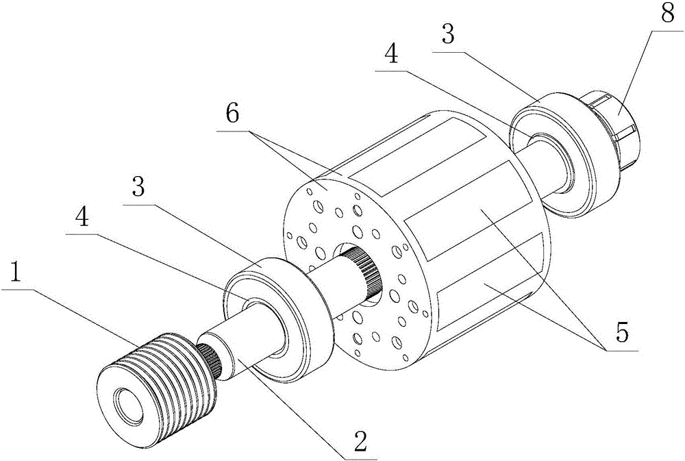
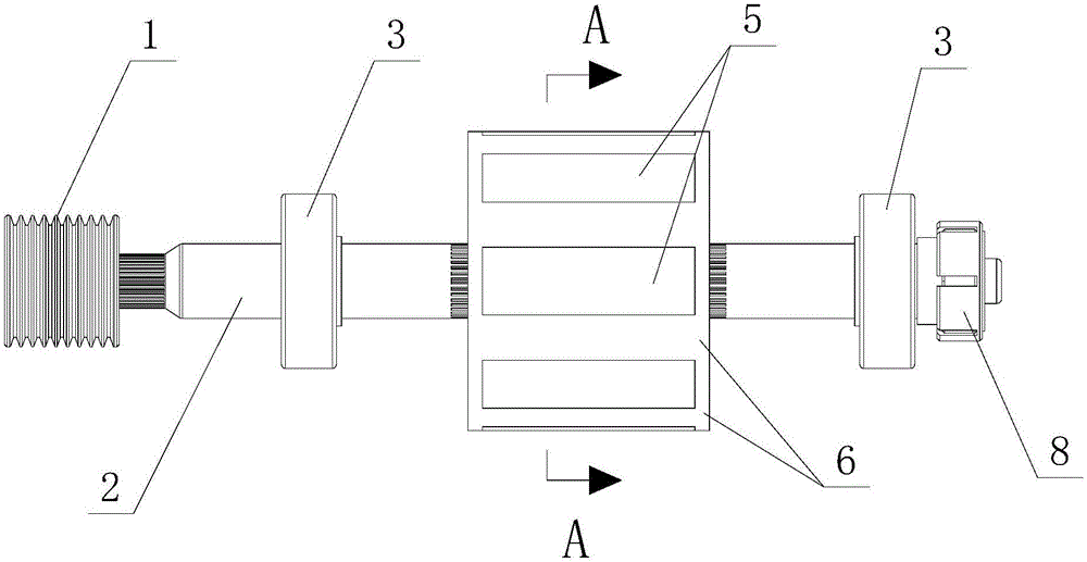
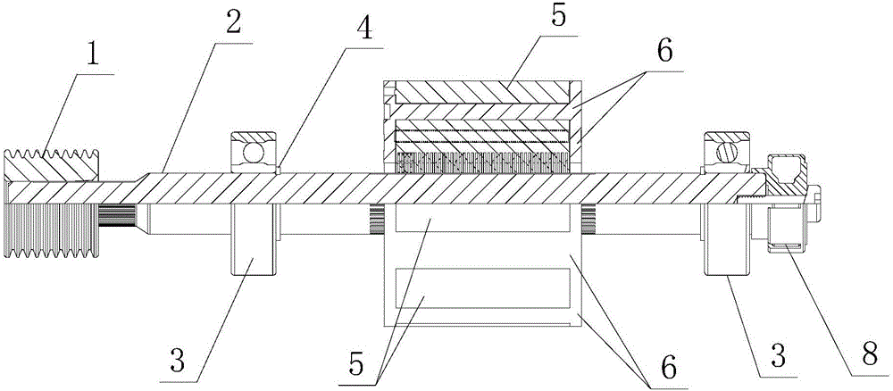
[0012] The present invention will now be described in further detail with reference to the drawings. The drawings are simplified schematic diagrams, which only illustrate the basic structure of the present invention in a schematic manner, and therefore only show the structures related to the present invention.

[0013] For specific examples, please refer to figure 1 , figure 2 , image 3 with Figure 4 , A high-efficiency rotor for a motor, comprising a rotating shaft 2, a bearing 3, a bearing fixing circlip 4, and a magnet 7. One end of the rotating shaft 2 is fixed with a pulley 1, and the other end of the rotating shaft 2 is fixed with a magnet ring 8. The bearing 3 is fixed on the rotating shaft 2 by a bearing fixing circlip 4, and the magnet 7 is sealed and fixed in the rotor core 5 by the injection molded plastic 6. The rotor core 5 and the magnet 7 are fixed in the injection molded plastic 6. A bearing 3 is fixed on both sides of the iron core 5 respectively.

[0014] The...


PUM


Abstract

The invention relates to the technical field of motors, in particular to a high-efficiency rotor for motors. The high-efficiency rotor for a motor includes a rotating shaft, a bearing, a bearing fixing ring and a magnet. The invention relates to a high-efficiency rotor for a motor. One end of the rotating shaft is fixed with a pulley and the other end is fixed with a magnet ring. The magnet is sealed in the rotor iron core by injection molding plastic, so that the structure of the rotor is more stable and the structure of the motor rotor is obtained. Higher quality and safety stability. In addition, the rotor structure of the novel motor is reasonable in design, easy to use and install, stable, and suitable for popularization and use.

Description

technical field [0001] The invention relates to the technical field of motors, in particular to a high-efficiency rotor for motors. Background technique [0002] The motor rotor is the rotating part in the motor. The motor consists of two parts, the rotor and the stator, which are used to realize the conversion of electrical energy and mechanical energy and mechanical energy and electrical energy. The motor rotor is divided into a motor rotor and a generator rotor. The motor rotor is divided into two types: inner rotor rotation mode and outer rotor rotation mode. The rotation mode of the inner rotor is that the core body in the middle of the motor is a rotating body, which outputs torque (referring to the motor) or receives energy (referring to the generator). The rotation mode of the outer rotor is to use the outer body of the motor as the rotating body, and different modes facilitate the application in various occasions. The chips in the common motor rotors are simply ...

Claims


Application Information

Patent Timeline
IPC IPC(8): H02K1/28H02K5/16
CPCH02K1/276H02K1/28H02K5/1675
Inventor 崔云镐
Owner 泰信电机(苏州)有限公司
Why Eureka
Try Eureka