Supercharge Your Innovation With Domain-Expert AI Agents!

fan

A technology of fan components and nozzles, which is applied in the direction of liquid variable displacement machines, liquid fuel engines, machines/engines, etc., and can solve problems such as damage to fan components

Active Publication Date: 2019-05-14
DYSON TECH LTD
View PDF11 Cites 0 Cited by
  • Summary
  • Abstract
  • Description
  • Claims
  • Application Information

AI Technical Summary

Problems solved by technology

This prevents the impeller from potentially drawing debris and dust into the fan assembly, which could damage the fan assembly

Method used


Image

  • fan
  • fan
  • fan

Examples


Embodiment Construction

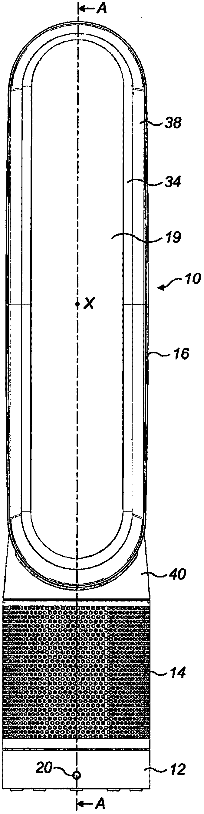
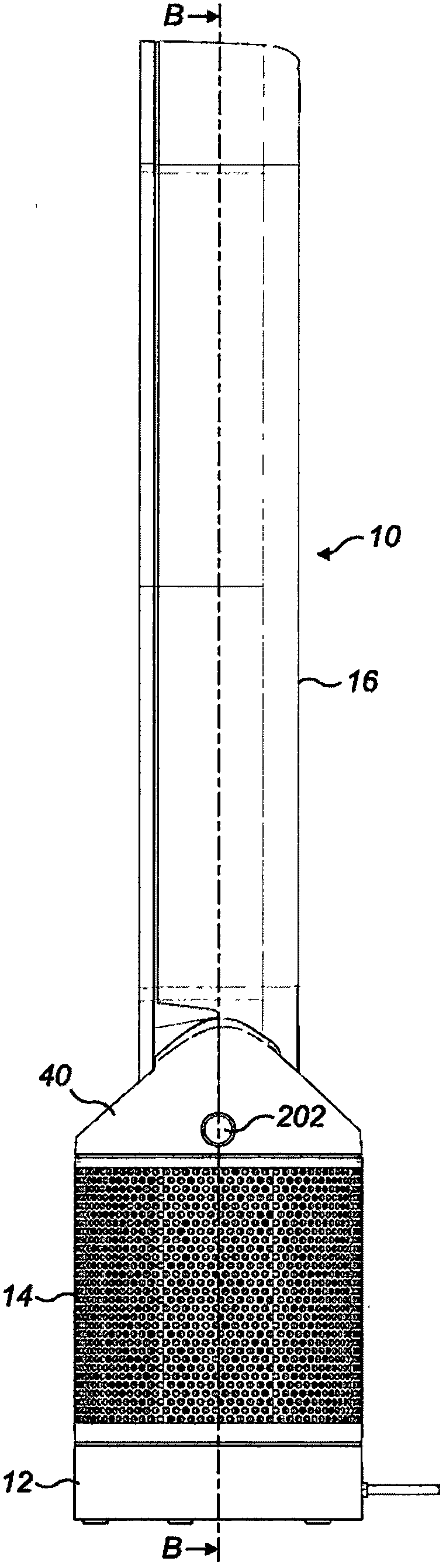
[0103] Figure 1 to Figure 3 is the external view of the fan 10, Figure 4 and 5 are shown along the figure 2 and image 3 Sectional view of the middle line A-A and B-B. exist Figure 4 As in FIG. 5 , the top of the nozzle is omitted in order to improve the clarity of the rest of the fan 10 . Generally, the fan includes a body 12, a removable filter 14 mounted on the body 12, and an annular nozzle 16 mounted on the body 12. The filter 14 is placed on an annular flange 54 extending radially outward from the body 12, the removal of which filter from the body being prevented by the presence of the nozzle 16. In order to remove the filter 14 from the fan 10, the nozzle 16 must first be removed.

[0104] The annular nozzle 16 has an air outlet 18 for emitting the main flow of air from the fan 10 and defines a hole 19 , or opening, through which air from outside the fan assembly 10 is drawn by the air emitted from the air outlet 18 . Body 12 further includes a user interface...


PUM


Abstract

A fan assembly comprising: a body including an inlet, an outlet and means for generating airflow; a nozzle mountable on the body for receiving airflow from the body and for emitting an airflow; nozzle retaining means, The nozzle is releasably retained on the body, the nozzle retainer having a first configuration in which the nozzle is retained on the body and a second configuration in which the nozzle is released for removal from the body removal; and, a manually actuatable member positioned on the nozzle for effecting movement of the nozzle retainer from the first configuration to the second configuration.

Description

technical field [0001] The invention relates to a fan. In particular, but not exclusively, the invention relates to a floor or table fan, such as a table fan, tower fan or floor fan. Background technique [0002] Conventional household fans typically include a set of blades or vanes mounted for rotation about an axis, and a drive for rotating the set of blades to generate an air flow. The movement and circulation of the air stream creates a "cool wind" or breeze, and as a result, the user experiences a cooling effect as heat is dissipated by convection and evaporation. The blades are typically located within a cage that allows air flow through the housing while preventing the user from coming into contact with the spinning blades during use of the fan. [0003] Document WO 2009 / 030879 describes a fan assembly that does not use blades housed in a shroud to blow air out of the fan assembly. Alternatively, the fan assembly includes a cylindrical base housing motor-driven pad...

Claims


Application Information

Patent Timeline
Patent Type & Authority Patents(China)
IPC IPC(8): F04B41/06F04F5/16F04F5/46F04F5/44
CPCF04B41/06F04F5/16F04F5/44F04F5/46F04D25/08F04D29/703F04D29/624F04D29/644F04D29/403F04D29/626F04D29/646F04D29/083
Inventor J·约翰逊S·E·皮特C·S·霍奇森L·J·加纳A·J·贝茨W·R·亨特
Owner DYSON TECH LTD
Features
  • R&D
  • Intellectual Property
  • Life Sciences
  • Materials
  • Tech Scout
  • Unparalleled Data Quality
  • Higher Quality Content
  • 60% Fewer Hallucinations
Learn More