

Machine vision light source device with light spot shape controllable and implementing method thereof
A light source device and machine vision technology, applied in the optical field, can solve problems such as low detection efficiency, inability to extract information, and limited applicability, and achieve the effects of uniform spatial distribution, improved detection efficiency, and simple and convenient operation
- Summary
- Abstract
- Description
- Claims
- Application Information
AI Technical Summary
Problems solved by technology
Method used
Image


Examples
Embodiment 1
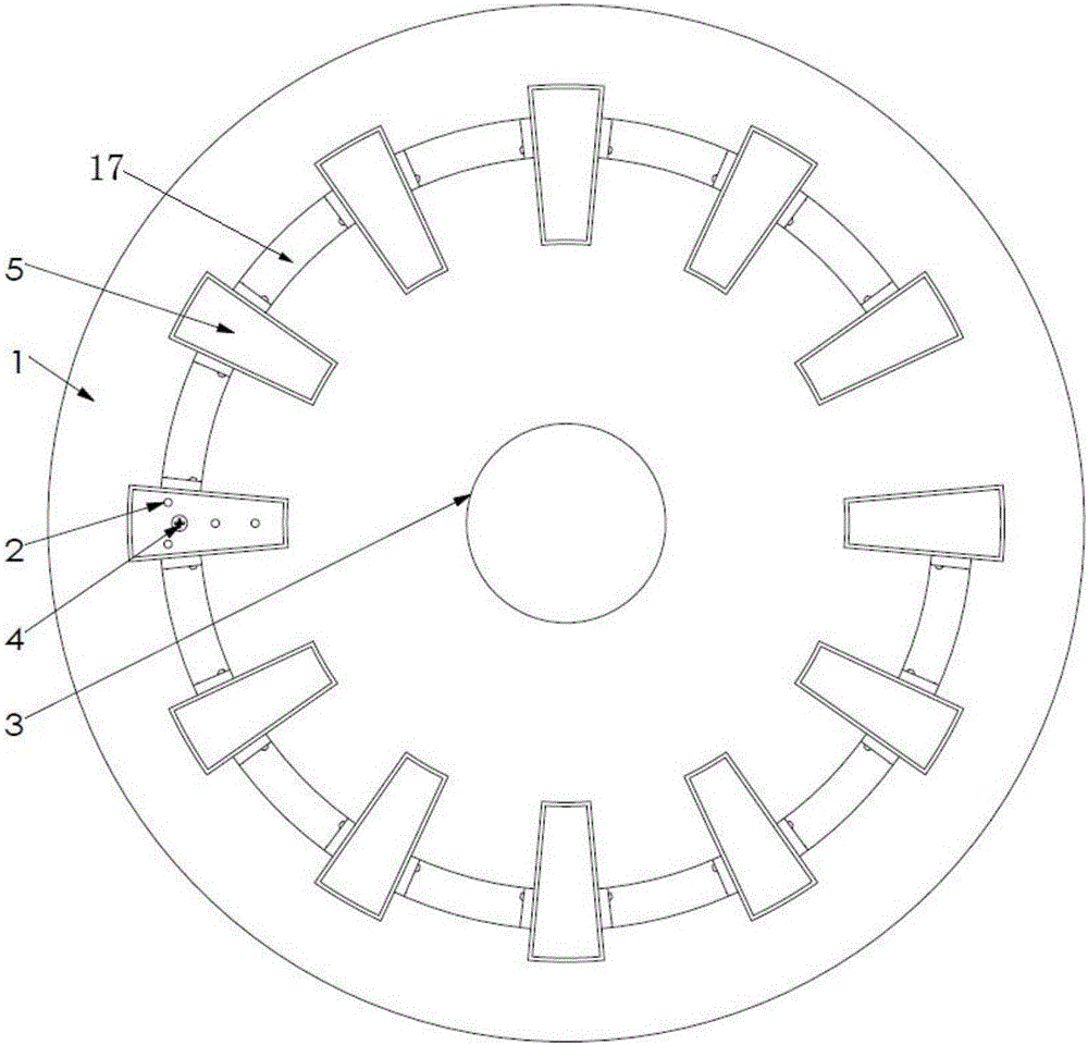
[0046] like figure 1 , 2 , 3, the machine vision light source device of the present invention includes a base plate 1, a housing 16, moving parts, a single-chip microcomputer and an LED module. The bottom plate 1 has a central hole 3 and an arc track 17, wherein the central hole 3 of the bottom plate 1 is the entrance of the machine vision system camera to collect images. The housing 16 also has a central hole 3 of the same size as the base plate. In addition, the moving parts include a large internal gear 6, a pinion 7, a small motor 8, a slider 10, a pulley 12 and a slider track. Wherein, the slider tracks include inner slider tracks 15 , 14 and outer slider tracks 13 , 11 . Small motor 8 is fixed on the slide block 10 by connecting piece (it is not drawn in accompanying drawing). Pinion 7 is connected with motor 8 output shaft by spline (it is not drawn in accompanying drawing). The pulley 12 is to reduce the frictional force of the slider 10 moving. Except for the la...
Embodiment 2
[0049] In order to facilitate operation, the housing 16 of a machine vision light source device with controllable spot shape of the present invention is equipped with the following buttons: "ON / OFF", "square", "circle", "triangle" and "hexagon", etc. .
[0050] The specific steps of the implementation method of the machine vision light source device of the present invention are:
[0051] S1. Fix the machine vision light source device with controllable spot shape on the image acquisition end of the machine vision inspection system, and make the axis of the camera align with the center hole 3 of the bottom plate and the center hole 3 of the housing.
[0052] S2. Adjust the machine vision light source device to the set lighting height.
[0053] S3. Place the detection part in the center of the lighting range, press the "ON / OFF" button of the light source, the light source works, and the light spot is circular at this time.
[0054] S4. Determine whether the part to be detected ...
PUM
 Abstract
Description
Claims
Application Information