Multifunctional automatic inner-high-pressure forming machine

A multifunctional technology of internal high pressure forming, which is applied in the field of multifunctional automatic internal high pressure forming machines, can solve the problems that it is not suitable for forming components with multiple branches on both sides, the axial feed mechanism cannot be automatically adjusted, and it is inconvenient to form axis bending components, etc. , to achieve the effect of facilitating the automatic production of equipment, improving the forming accuracy and automation level of equipment, and improving the working efficiency of equipment

Active Publication Date: 2016-09-28
GUILIN UNIV OF ELECTRONIC TECH
View PDF11 Cites 3 Cited by
  • Summary
  • Abstract
  • Description
  • Claims
  • Application Information

AI Technical Summary

Problems solved by technology

[0007] The purpose of the present invention is to solve the problem that the existing internal high pressure forming machine has a single function, is not suitable for forming components with multiple branches on both sides, is not convenient for forming axis bending components, and cannot autom

Method used


Image

  • Multifunctional automatic inner-high-pressure forming machine
  • Multifunctional automatic inner-high-pressure forming machine
  • Multifunctional automatic inner-high-pressure forming machine

Examples


Embodiment 1

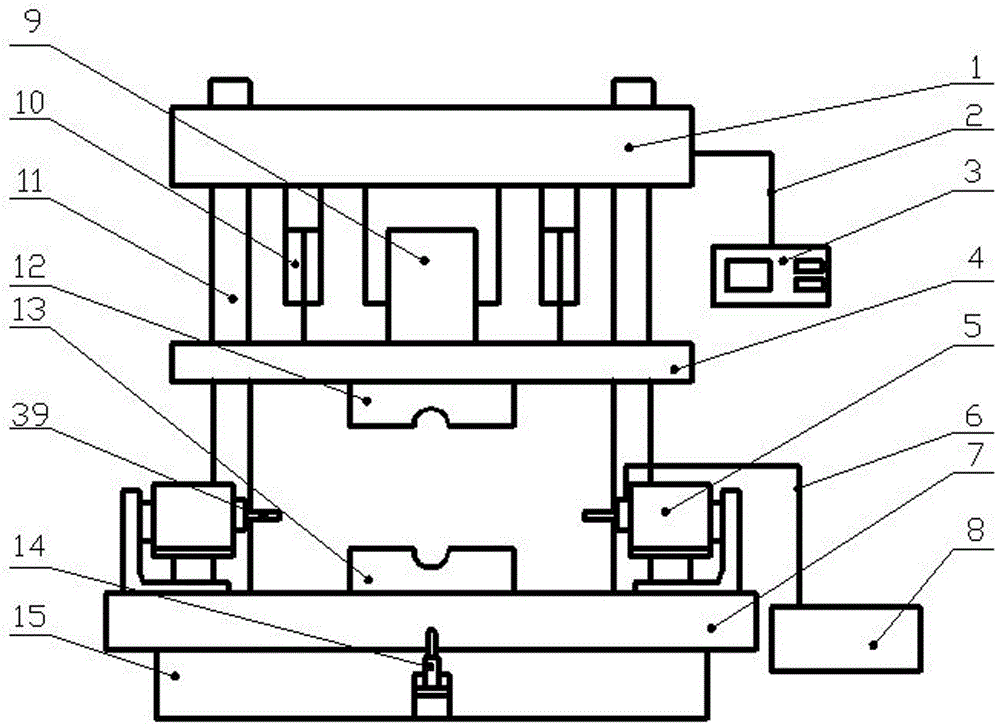
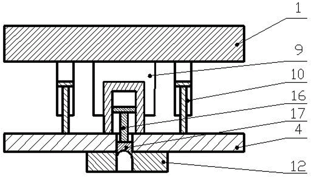
[0032] Such as figure 1 , image 3 , Image 6As shown, a multifunctional automatic internal high pressure forming machine of the present invention includes: an upper beam 1, a movable beam 4, a workbench 7, a frame 15, a cable 2, a control panel 3, and at least 2 sets of adjustment and feeding combination mechanisms 5 A plurality of punches 39, high-pressure source 8, high-pressure water pipe 6, main clamping cylinder 9, 2 fast cylinders 10, 4 guide pillars 11, main upper mold 12, auxiliary upper mold 17, lower mold with the same number 13. At least one set of lower ejection and back pressure combination mechanisms 14 and the same number of ejector pins 30.

[0033] The four guide pillars 11 pass through the movable beam 4 corresponding to four holes, the upper end is fixedly connected with the upper beam, and the lower end is fixedly connected with the workbench 7, and the movable beam 4 can be moved under the guidance of the guide pillar 11 for mold clamping or mold openin...

Embodiment 2

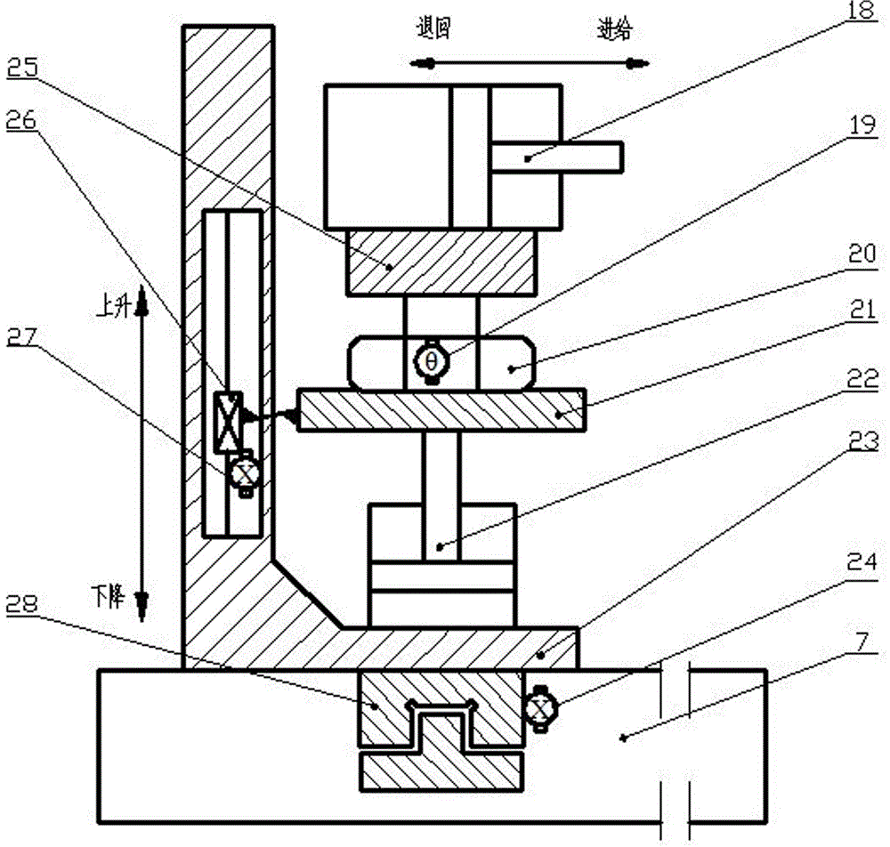
[0040] Such as figure 2 , image 3 , Figure 4 , Figure 7 As shown, in this example, input commands in the control panel 3 to make the hydraulic swing cylinder 20 drive the swing platform 25 to swing to a certain angle, so that the left and right punches 39 are facing the left and right ports of the pipe 41, and the angle formed is the same as the bending angle of the pipe. Identical; Subsequent shaping action is identical with embodiment 1.

Embodiment 3

[0042] Such as figure 2 , image 3 , Figure 5 , Figure 8 As shown, after the punch 39 is adjusted in place, an instruction is input in the control panel 3 to drive the lower and lower material left and right moving cylinder 37 to drive the lower and lower material left and right moving platform 35 to adjust to a suitable position under the guidance of the guide rail 36, and through the displacement sensor 38 The closed-loop feedback adjustment ensures the positioning accuracy; then the lower material return swing cylinder 32 moves to drive the lower material return cylinder 31 to swing to a suitable angle, and through the feedback adjustment of the angle sensor 38, the swing angle accuracy is guaranteed and locked during the forming process; the lower material return Cylinder 31 goes up to drive the ejector rod 30 to a proper position; after the main upper mold 12 is closed, the upper ejector cylinder 16 moves downward to drive the auxiliary upper mold 17 to move to a sui...


PUM


Abstract

The invention discloses a multifunctional automatic inner-high-pressure forming machine. The multifunctional automatic inner-high-pressure forming machine comprises an upper transverse beam, a movable transverse beam, a workbench, a machine frame, a cable, a control panel, at least two sets of axial adjusting and feeding combination mechanisms, a plurality of plunger chips, a high-pressure source, a high-pressure water pipe, a main die closing cylinder, an upper discharging cylinder, two quick cylinders, four guiding columns, a main upper die, an auxiliary upper die, a lower die, at least one set of lower discharging backpressure combination mechanism and at least one jacking rod, wherein the number of the plunger chips is the same as that of the axial adjusting and feeding combination mechanisms, and the number of the jacking rod is the same as that of the lower discharging backpressure combination mechanism. According to the multifunctional automatic inner-high-pressure forming machine, two four-freedom-degree axial feeding mechanisms, the upper discharging cylinder and at least one lower discharging cylinder are arranged, a bent axis component and a component with multiple branch pipes on the two sides can be formed, and the equipment process application range is substantially expanded; the plunger chip swinging angles in the front position, the back position, the upper position, the lower position and the plane of the workbench are quickly and precisely controlled; manual adjustment is avoided, the forming precision is improved, and equipment automatic production is facilitated; and the operating speed is increased, energy sources are saved, and the equipment working efficiency is improved.

Description

technical field [0001] The invention relates to an internal high pressure forming machine, in particular to a multifunctional automatic internal high pressure forming machine. Background technique [0002] Internal high pressure forming technology for pipes is an advanced, special, precise (semi-precision) near-net forming technology for producing thin-walled components with complex cross-sections. It has the characteristics of low cost, less process, light weight and high rigidity. An advanced material manufacturing technology that realizes the structural integration and lightweight of parts and components, and is widely used in aviation, automobiles, home appliances and other industrial fields. For example, multi-pass oil pipes of aero-engines, exhaust pipes, sub-frames and chassis of automobiles, and multi-branch copper pipes for heating of central air-conditioning, all of which are gradually replaced by traditional forming methods with internal high-pressure forming meth...

Claims


Application Information

Patent Timeline
IPC IPC(8): B21D26/037B21D26/045B21D26/043B21D26/039
CPCB21D26/037B21D26/039B21D26/043B21D26/045
Inventor 杨连发张明河李坤翟志方付永佩
Owner GUILIN UNIV OF ELECTRONIC TECH
Why Eureka
Try Eureka