Supercharge Your Innovation With Domain-Expert AI Agents!

Lifting sling

A spreader and hook technology, applied in the field of lifting, can solve problems such as difficult installation, decoupling, no spreader, etc., and achieve the effects of increased service life, convenient installation and disassembly, and ingenious structure

Active Publication Date: 2016-09-28
成都宝钢汽车钢材部件加工配送有限公司
View PDF6 Cites 3 Cited by
  • Summary
  • Abstract
  • Description
  • Claims
  • Application Information

AI Technical Summary

Problems solved by technology

[0002] At present, the spreaders on the market are basically general-purpose spreaders, but for some non-standard racks, general-purpose spreaders are not suitable
In particular, the material racks provided by some automobile manufacturers are special material racks in their factories, and this kind of material racks are only suitable for ground transportation, and there is no special supporting spreader, so it is very inconvenient to use a crane to transport
[0003] The material rack provided by the Volvo factory is not equipped with lifting rings. In order to adapt to the production in the factory, the upper surface of the material rack is very flat, and it is not possible to install additional lifting rings. Only the protruding eaves on the side can be used to install the lifting gear.
However, using the existing sling is not only difficult to install, but also easy to damage the upper surface of the material rack, and at the same time cannot achieve locking, which is prone to accidents caused by decoupling

Method used


Image

  • Lifting sling
  • Lifting sling
  • Lifting sling

Examples


Embodiment 1

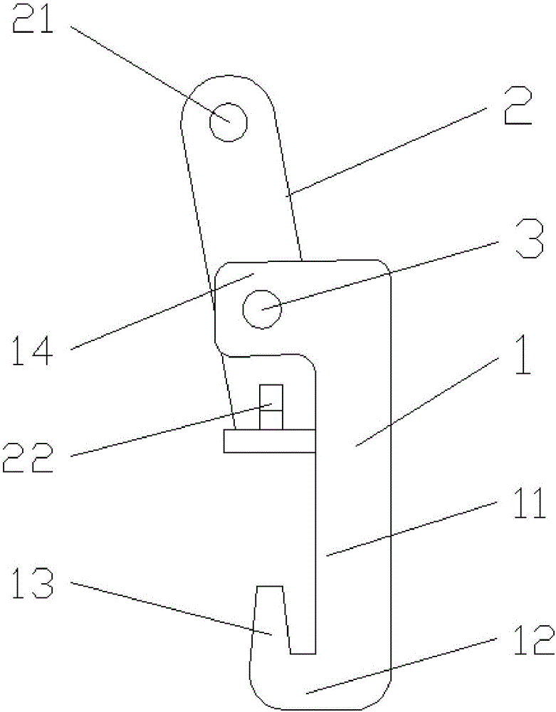
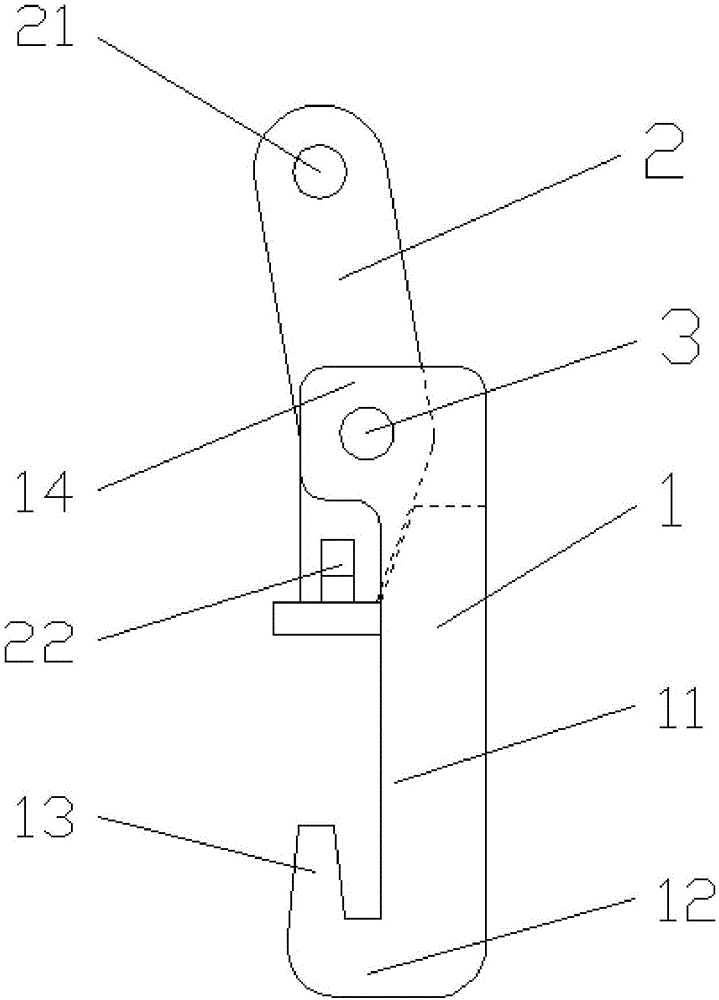
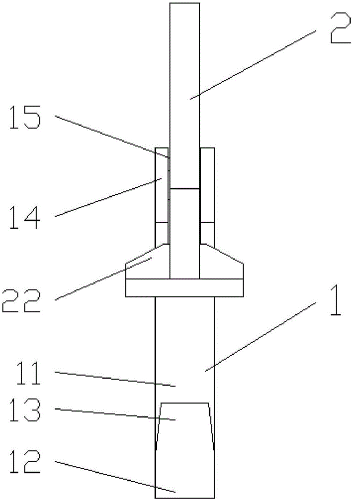
[0030] Such as figure 1 As shown, a suspension includes a hook 1 and a fixing member 2. The hook 1 includes a straight arm 11, a cross arm 12, and a hook portion 13. The bottom end of the straight arm 11 is connected to one end of the cross arm 12, and the cross arm 12 The other end of the straight arm 11 is connected to the hook 13, and the top of the straight arm 11 is provided with a transverse lug 14, the lug 14 faces the side of the hook 13, and the top surface of the straight arm 11 has a through groove 15, and the through groove 15 runs through the lug 14 The fixed part 2 passes through the through groove 15, the fixed part 2 is connected with the lug 14 by the pin shaft 3, the width of the bottom part of the fixed part 2 is greater than the width of the through groove 15, and the upper part of the fixed part 2 is provided with a hoisting hole 21, and the fixed part 2 The bottom is provided with reinforcing ribs 22, and the bottom surface of the fixing part 2 is a plane...

Embodiment 2

[0032] On the basis of Embodiment 1, the fixing part 2 is a bar-shaped plate, and the central axis of the upper part of the fixing part 2 and the central axis of the lower part of the fixing part 2 form an angle of 10°.

[0033] Installation method of the present invention (the same as embodiment one and embodiment two):

[0034] Such as Figure 4 As shown, rotate the fixing part 2 to turn the lower part of the fixing part 2 to the level, then use the hook part 13 of the hook 1 to hook the lower eaves on the side of the material rack 4, and then reversely rotate the fixing part 2 to make the bottom of the fixing part 2 The lower part is close to the inner wall of the straight arm 11, the lower surface of the fixing part 2 just touches the upper surface of the material rack 4, and then is connected with the hanging chain through the hoisting hole 21. Due to the gravity of the hanging chain itself, the hanging chain will swing to the material rack 4 center, so the hanging chain...


PUM


Abstract

The invention discloses a lifting sling, and belongs to the technical field of hoisting. The lifting sling comprises a lifting hook and a fixing part, the lifting hook comprises a straight arm, a cross arm and a hook part, the bottom end of the straight arm is connected with one end of the cross arm, the other end of the cross arm is connected with the hook part, a transverse convex lug is arranged at the top of the straight arm and faces one side of the hook part, and a through groove is formed in the top face of the straight arm and goes through the convex lug; the fixing part penetrates through the through groove and is connected with the convex lug through a pin roll, the width of the bottom of the fixing part is larger than that of the through groove, and a hoisting hole is formed in the upper portion of the fixing part. The lifting sling is suitable for a Volvo material frame, convenient to install without damaging the upper surface of the material frame and capable of being locked and prevents accidents caused by unhooking.

Description

technical field [0001] The invention relates to a lifting technology, in particular to a spreader. Background technique [0002] At present, the spreaders on the market are basically general-purpose spreaders, but for some non-standard racks, general-purpose spreaders are not suitable. Especially the material racks provided by some automobile manufacturers are special material racks in their factories, and this material racks are only suitable for ground transportation. There is no special supporting spreader, and it is very inconvenient to use a crane to transport. [0003] The material rack provided by the Volvo factory is not equipped with lifting rings. In order to adapt to the production in the factory, the upper surface of the material rack is very flat, and it is impossible to install additional rings. However, the existing sling is not only difficult to install, but also easily damages the upper surface of the material rack, and cannot realize locking at the same ti...

Claims


Application Information

Patent Timeline
Patent Type & Authority Applications(China)
IPC IPC(8): B66C1/24
CPCB66C1/24
Inventor 淳子力代小东赵灿
Owner 成都宝钢汽车钢材部件加工配送有限公司
Features
  • R&D
  • Intellectual Property
  • Life Sciences
  • Materials
  • Tech Scout
  • Unparalleled Data Quality
  • Higher Quality Content
  • 60% Fewer Hallucinations
Learn More