Laser beam combining apparatus

A laser beam combination and laser technology, applied in the laser field, can solve the problems that the lasers cannot be very close, the output power density is difficult to further increase, and the distance between the lasers is large, etc., and achieve the effect of strong implementability, reasonable configuration, and simple principle

Inactive Publication Date: 2016-09-28
BWT BEIJING
View PDF6 Cites 7 Cited by
  • Summary
  • Abstract
  • Description
  • Claims
  • Application Information

AI Technical Summary

Problems solved by technology

[0003] Among them, in the existing laser beam combining technology, the light-emitting units of the multi-beam lasers that need to be combined, that is, multiple lasers, are placed on the base. Usually, due to the limitation of the micro-channel structure, the optical alignment system Due to factor

Method used


Image

  • Laser beam combining apparatus
  • Laser beam combining apparatus
  • Laser beam combining apparatus

Examples


Example Embodiment

[0035] Hereinafter, exemplary embodiments of the present disclosure will be described in more detail with reference to the accompanying drawings. Although exemplary embodiments of the present disclosure are shown in the drawings, it should be understood that the present disclosure can be implemented in various forms and should not be limited by the embodiments set forth herein. On the contrary, these embodiments are provided to enable a more thorough understanding of the present disclosure and to fully convey the scope of the present disclosure to those skilled in the art.

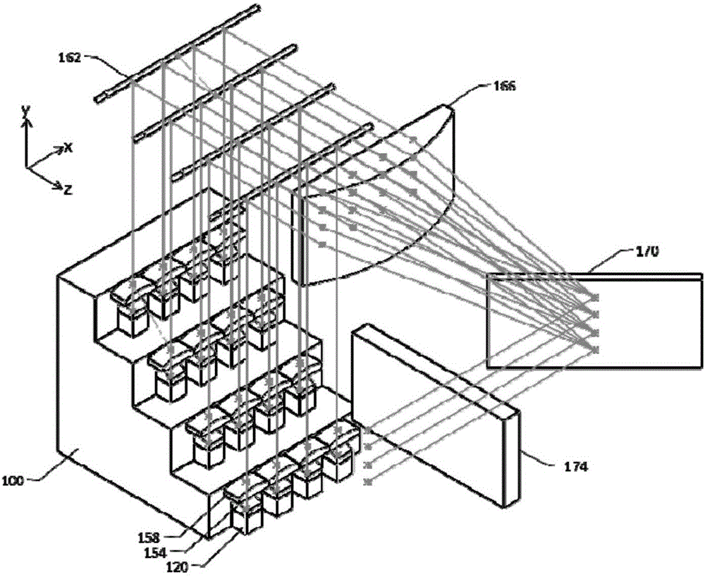
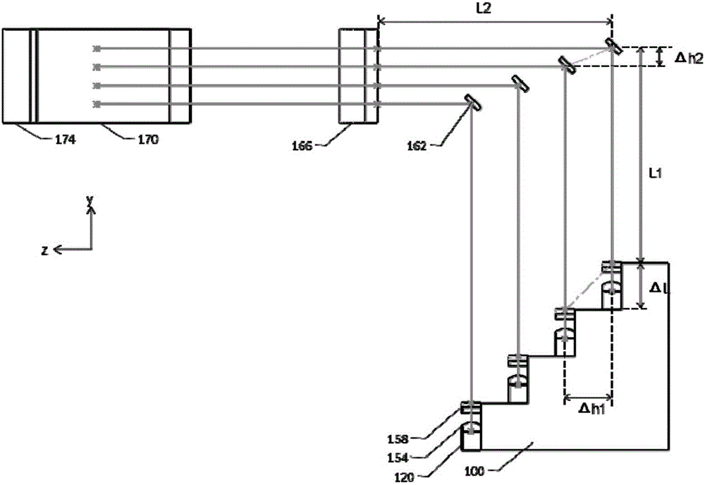
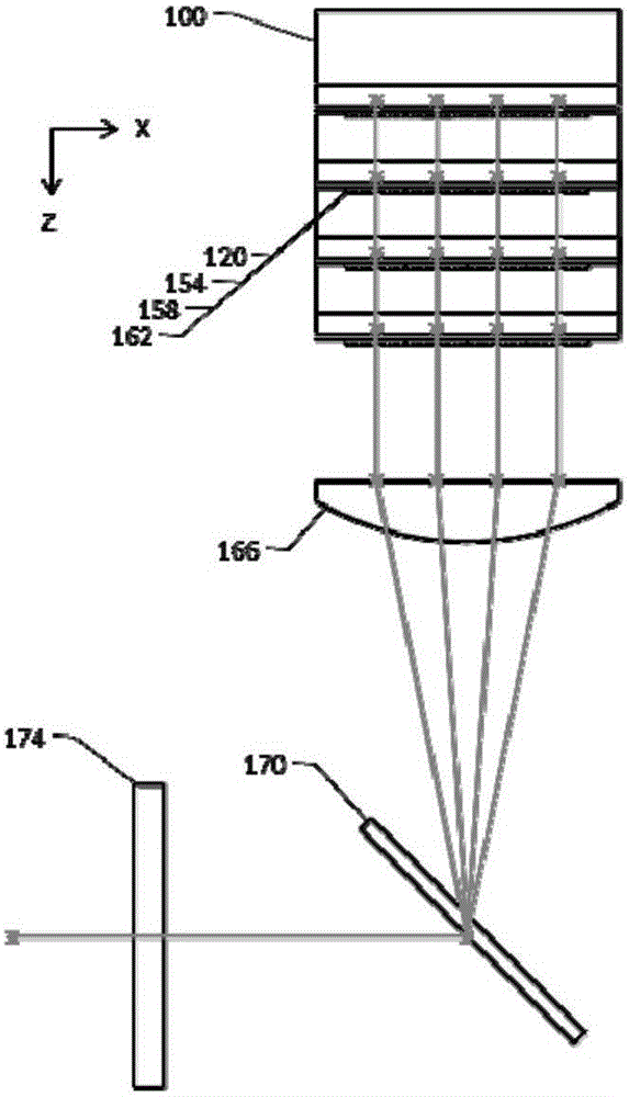
[0036] Establish the x-axis, y-axis and z-axis, the x-axis is the horizontal axis, the z-axis is the vertical axis, and the y-axis is the vertical axis, forming a right-handed space rectangular coordinate system xyz, according to the right-handed space rectangular coordinate system, the spatial combination provided by the present invention The device and the system are described. In the following embodiments,...


PUM


Abstract

The invention discloses a laser beam combining apparatus. The laser beam combining apparatus comprises a laser array, turning optical elements, a conversion lens, a dispersion element and an external cavity mirror, wherein the laser array comprises M rows of lasers, and each row of lasers comprise N lasers; M*N beams of laser output by the laser array, after passing through the turning optical elements, are emitted in parallel, N beams of laser corresponding to each row of lasers form a coplanar laser array, and planes where M laser arrays are disposed are parallel, and adjacent intervals are specific distances; the N beams of laser in each laser array, after being converged by the conversion lens, are respectively incident to the dispersion element through different angles; and the N beams of laser in each laser array, after passing through the dispersion element, are combined to form one beam of output light, and the M beams of output light corresponding to the M laser arrays, after passing through the external cavity mirror, are output in parallel. According to the invention, since a turning structure is employed, multiple beams of laser output by the laser array are closely arranged, and while the heat dissipation performance of the laser array is improved, higher-efficiency laser beam combination is realized.

Description

technical field [0001] The invention relates to the field of laser technology, in particular to a laser beam combining device. Background technique [0002] Laser beam combining technology is a process of improving beam quality, increasing output power, and increasing power density. Commonly used laser beam combining methods include spectral beam combining, spatial beam combining and polarization beam combining. These laser beam combining methods can be used alone. In some A combination of different laser beam combining methods can also be used in the scene. [0003] Among them, in the existing laser beam combining technology, the light-emitting units of the multi-beam lasers that need to be combined, that is, multiple lasers, are placed on the base. Usually, due to the limitation of the micro-channel structure, the optical alignment system Due to structural constraints and other factors, the distance between lasers in the laser array that can be realized is relatively larg...

Claims


Application Information

Patent Timeline
IPC IPC(8): H01S3/04H01S3/10H01S3/23
CPCG02B27/10H01S5/14H01S5/40H01S3/0407H01S3/10H01S3/10053H01S3/23
Inventor 郭渭荣王宝华郭志婕徐丹徐磊陈晓华
Owner BWT BEIJING
Why Eureka
Try Eureka