Check patentability & draft patents in minutes with Patsnap Eureka AI!

A mechanical arm travel limit device for an automatic lathe

A technology of mechanical arm and stroke limit, applied in the direction of auxiliary devices, turning equipment, toolholder accessories, etc., can solve the problems of low safety performance, hidden safety hazards, low work efficiency, etc., and achieve improved safety and supervision, automation High degree of protective effect

Inactive Publication Date: 2018-10-12
韩永亮
View PDF6 Cites 0 Cited by
  • Summary
  • Abstract
  • Description
  • Claims
  • Application Information

AI Technical Summary

Problems solved by technology

[0002] In the process of using the traditional lathe to process the motor end cover, it is necessary to manually load the material and then process it through the lathe. This traditional processing mode has low work efficiency and is laborious. Therefore, an automatic lathe has been developed. When using this kind of automatic lathe to process the motor end cover, the mechanical arm moves on the walking bracket, and the automatic grabbing device is used to grab and move the workpiece to be processed to complete the loading work, and the mechanical arm walks on the walking bracket. It is necessary to use a limit device to limit its stroke, but the structure design of the existing stroke limit device is generally relatively common, the function is not stable enough, and the safety performance is low. Once the limit member fails, there will be a great safety hazard. There are certain defects. Therefore, it is of great significance to develop a mechanical arm travel limit device for automatic lathes with comprehensive functions, safety and high efficiency, high degree of automation, and real-time monitoring.

Method used


Image

  • A mechanical arm travel limit device for an automatic lathe
  • A mechanical arm travel limit device for an automatic lathe

Examples


Embodiment 1

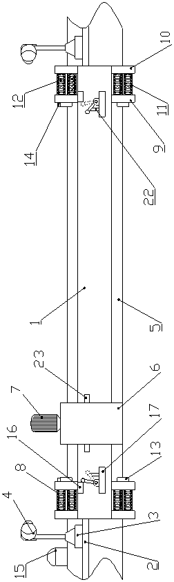
[0015] Such as figure 1 , figure 2 As shown, a mechanical arm travel limit device for an automated lathe, which includes a walking main beam 1, the left middle and right middle of the walking main beam 1 are provided with a support seat A2, and the upper end of the support seat A2 is connected with The base 3 and the rotatable camera 4 matched with the base 3, the upper and lower ends of the front side of the middle part of the walking main beam 1 are provided with a walking track 5, and the walking track 5 is connected with a mechanical arm component 6. The mechanical arm The component 6 is connected with a drive motor 7, and the left and right ends of the walking track 5 are provided with a collision buffer device 8, and the collision buffer device 8 is provided with an inner support plate 9 and an outer support plate 10, and the inner support plate 9 and The inner side of the outer support plate 10 is connected with a buffer body 11, the inner cavity of the buffer body 11...

Embodiment 2

[0017] Such as figure 1 , figure 2 As shown, a mechanical arm travel limit device for an automated lathe, which includes a walking main beam 1, the left middle and right middle of the walking main beam 1 are provided with a support seat A2, and the upper end of the support seat A2 is connected with The base 3 and the rotatable camera 4 matched with the base 3, the upper and lower ends of the front side of the middle part of the walking main beam 1 are provided with a walking track 5, and the walking track 5 is connected with a mechanical arm component 6. The mechanical arm The component 6 is connected with a drive motor 7, and the left and right ends of the walking track 5 are provided with a collision buffer device 8, and the collision buffer device 8 is provided with an inner support plate 9 and an outer support plate 10, and the inner support plate 9 and The inner side of the outer support plate 10 is connected with a buffer body 11, the inner cavity of the buffer body 11...


PUM


Abstract

The invention relates to a mechanical arm stroke limiting device for an automatic lathe. The mechanical arm stroke limiting device comprises a walking main beam, wherein the left middle part and the right middle part of the walking beam are separately provided with a support base A and a rotatable camera; the walking main beam is provided with a walking rail and a mechanical arm component which is connected with a driving motor; the walking rail is provided with impact buffering devices; the inner side of each impact buffering device is connected with an elastic impact block; the upper end of each elastic impact block is connected with a microswitch; each microswitch is connected with an alarming device through a signal wire; the lower sides of the left upper part and the right upper part of the walking rail are connected with stroke switches; the stroke switches are connected with the driving motor through signal wires; the walking main beam is provided with support bases B; the upper end of the left part of each support base B is connected with a rotary rod and a ball-shaped magnet through a connection lug and a pin; the upper end of the right part of each support base B is connected with a baffle block; and the middle part of each of the left and right sides of the mechanical arm component is provided with an electrical magnet. The mechanical arm stroke limiting device has the advantages that the functions are complete; safety and high-efficiency are realized; the automation degree is high; and real-time monitoring is realized.

Description

technical field [0001] The invention belongs to the technical field of parts and components of an automatic lathe, and in particular relates to a stroke limiting device of a mechanical arm of an automatic lathe. Background technique [0002] In the process of using the traditional lathe to process the motor end cover, it is necessary to manually load the material and then process it through the lathe. This traditional processing mode has low work efficiency and is laborious. Therefore, an automatic lathe has been developed. When using this kind of automatic lathe to process the motor end cover, the mechanical arm moves on the walking bracket, and the automatic grabbing device is used to grab and move the workpiece to be processed to complete the loading work, and the mechanical arm walks on the walking bracket. It is necessary to use a limit device to limit its stroke, but the structure design of the existing stroke limit device is generally relatively common, the function i...

Claims


Application Information

Patent Timeline
Patent Type & Authority Patents(China)
IPC IPC(8): B23B25/06B23B15/00
CPCB23B25/06B23Q7/00
Inventor 韩永亮
Owner 韩永亮
Features
  • R&D
  • Intellectual Property
  • Life Sciences
  • Materials
  • Tech Scout
  • Unparalleled Data Quality
  • Higher Quality Content
  • 60% Fewer Hallucinations
Learn More