Check patentability & draft patents in minutes with Patsnap Eureka AI!

Turbine housing and associated exhaust turbocharger

A technology for exhaust turbines and turbines, which is applied in the direction of machines/engines, gas turbine devices, mechanical equipment, etc., and can solve problems such as failure of exhaust turbochargers, and achieve the effects of reducing costs, reducing weight, and reducing material usage

Inactive Publication Date: 2019-11-19
BOSCH MAHLE TURBO SYST GMBH & CO KG
View PDF6 Cites 0 Cited by
  • Summary
  • Abstract
  • Description
  • Claims
  • Application Information

AI Technical Summary

Problems solved by technology

In most applications, said cracks grow further during the further course of operation and, in the worst case, can lead to through cracks which eventually lead to a complete blowout of the exhaust gas turbocharger due to the ensuing hot gas leakage. fail

Method used


Image

  • Turbine housing and associated exhaust turbocharger
  • Turbine housing and associated exhaust turbocharger

Examples


Embodiment Construction

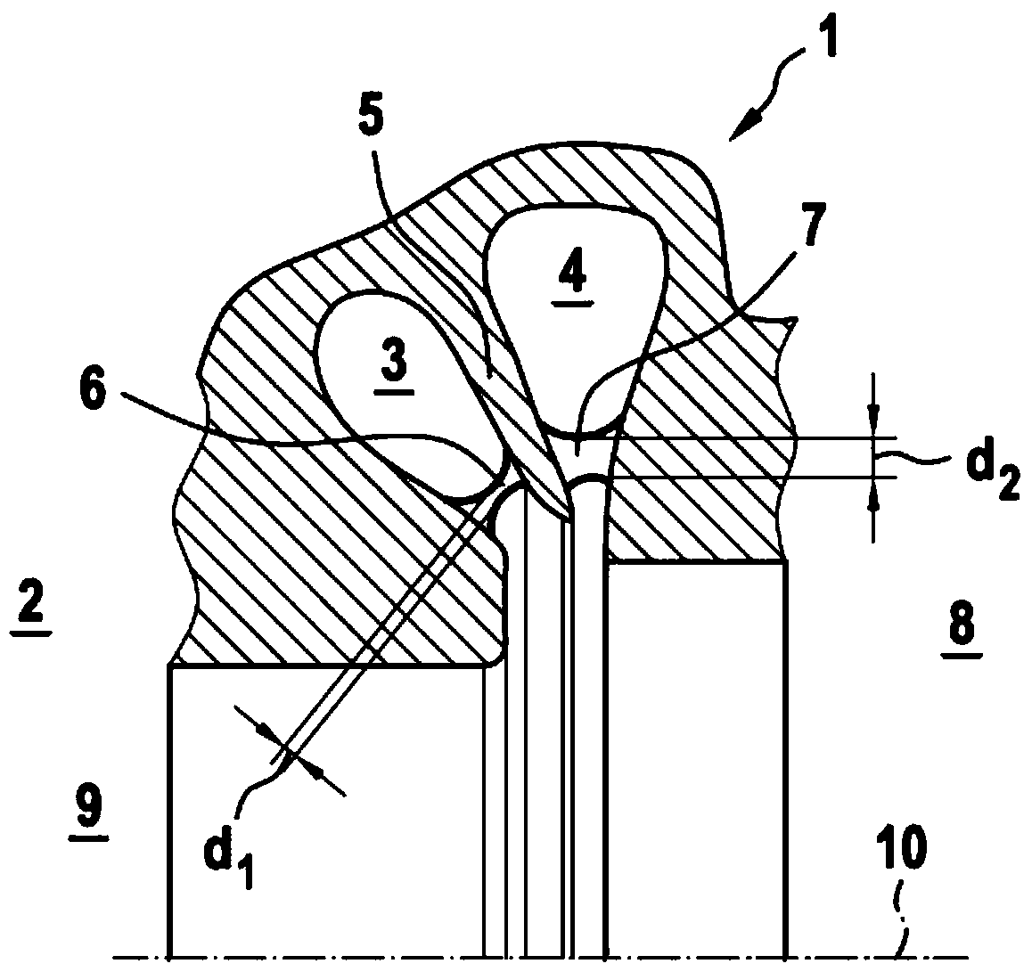
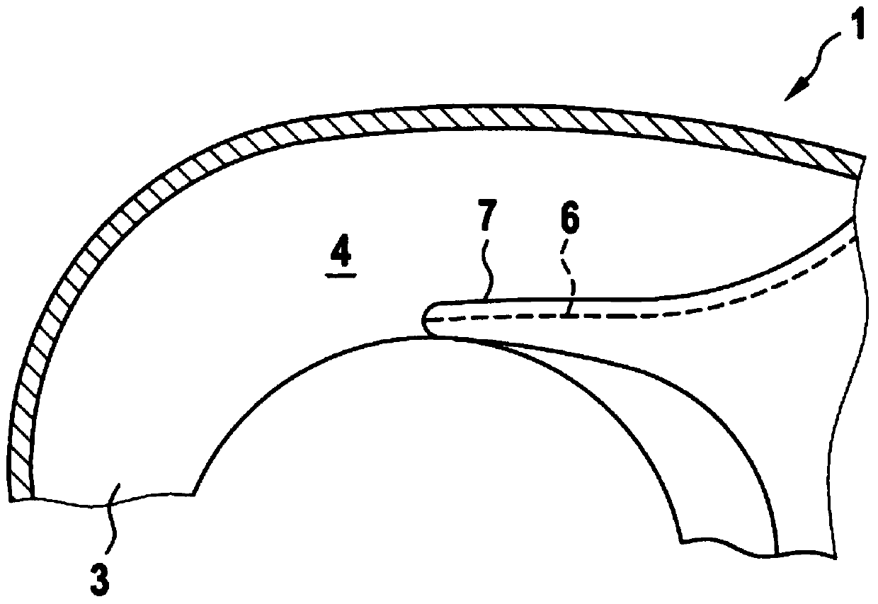
[0016] corresponds to figure 1 and figure 2 , the turbine housing 1 according to the invention has an exhaust turbocharger 2 (or not shown) and has two helical exhaust channels 3, 4 through which The partitions 5 are separated from each other and are delimited radially to the outside by the turbine housing 1 and in each case by a screw tongue 6 , 7 to the inside. In this case, in the direction of the turbine housing 1 the two screw tongues 6 , 7 extend in opposite directions away from the web 5 . here, figure 1 Only the upper half of the turbine housing 1 is shown, wherein the exhaust channel 4 is arranged adjacent to the bearing housing 8 and the exhaust channel 3 is arranged adjacent to the exhaust pipe 9 . In this case, during operation of the exhaust-gas turbocharger 2 , in particular the second screw tongue 7 is exposed to high thermal loads and is therefore at risk of cracks forming, wherein, in the event of a crack forming in the second screw tongue 7 , The crack p...


PUM


Abstract

A turbine housing of an exhaust-gas turbocharger may include at least two spiral-shaped exhaust-gas channels separated from one another via a partition. The at least two channels may be delimited radially to the outside by the turbine housing and radially to the inside by at least two spiral tongues. A first spiral tongue may be associated with one of the channels and a second spiral tongue may be associated with the other of the channels. The at least two spiral tongues may extend in opposite directions away from the partition in a direction towards the turbine housing. According to an example, the at least two spiral tongues may be configured such that, under an increasing thermomechanical loading, the first spiral tongue fails before the second spiral tongue.

Description

technical field [0001] According to the preamble of claim 1 , the invention relates to a turbine housing having two helical exhaust ducts which are separated from one another by a partition. The invention also relates to an exhaust-gas turbocharger with a turbine housing of the type described. Background technique [0002] In exhaust-gas turbochargers, a twin-channel turbine housing (so-called twin-helical turbine housing) is often used, which has two helical exhaust channels separated from each other over the entire length of the exhaust-gas turbine. The two helical or exhaust ducts are delimited radially towards the outside by the helical outer wall of the turbine housing and are delimited radially towards the inside by two tongue-shaped turbine housings protruding into the exhaust gas inlet of the exhaust turbine limit. In the axial direction, the two exhaust channels are separated from each other by a so-called partition. Both spiral tongues are subjected to extremely...

Claims


Application Information

Patent Timeline
Patent Type & Authority Patents(China)
IPC IPC(8): F01D25/24F02C6/12
CPCF01D25/24F02C6/12F01D1/00F01D9/026F01D9/045F02B37/001Y02T10/12F04D17/12F04D29/4206
Inventor 弗洛里安·埃尔代
Owner BOSCH MAHLE TURBO SYST GMBH & CO KG
Features
  • R&D
  • Intellectual Property
  • Life Sciences
  • Materials
  • Tech Scout
  • Unparalleled Data Quality
  • Higher Quality Content
  • 60% Fewer Hallucinations
Learn More