Supercharge Your Innovation With Domain-Expert AI Agents!

brake force control

A control device and braking force technology, applied in the direction of the brake, etc., can solve the problem of reducing the braking feel

Active Publication Date: 2018-10-12
TOYOTA JIDOSHA KK
View PDF5 Cites 0 Cited by
  • Summary
  • Abstract
  • Description
  • Claims
  • Application Information

AI Technical Summary

Problems solved by technology

For example, if braking is initiated when the driver feels that the moment the brakes become active is delayed relative to the moment when the brakes actually become effective, the brake feel is reduced

Method used


Image

  • brake force control
  • brake force control
  • brake force control

Examples


Embodiment

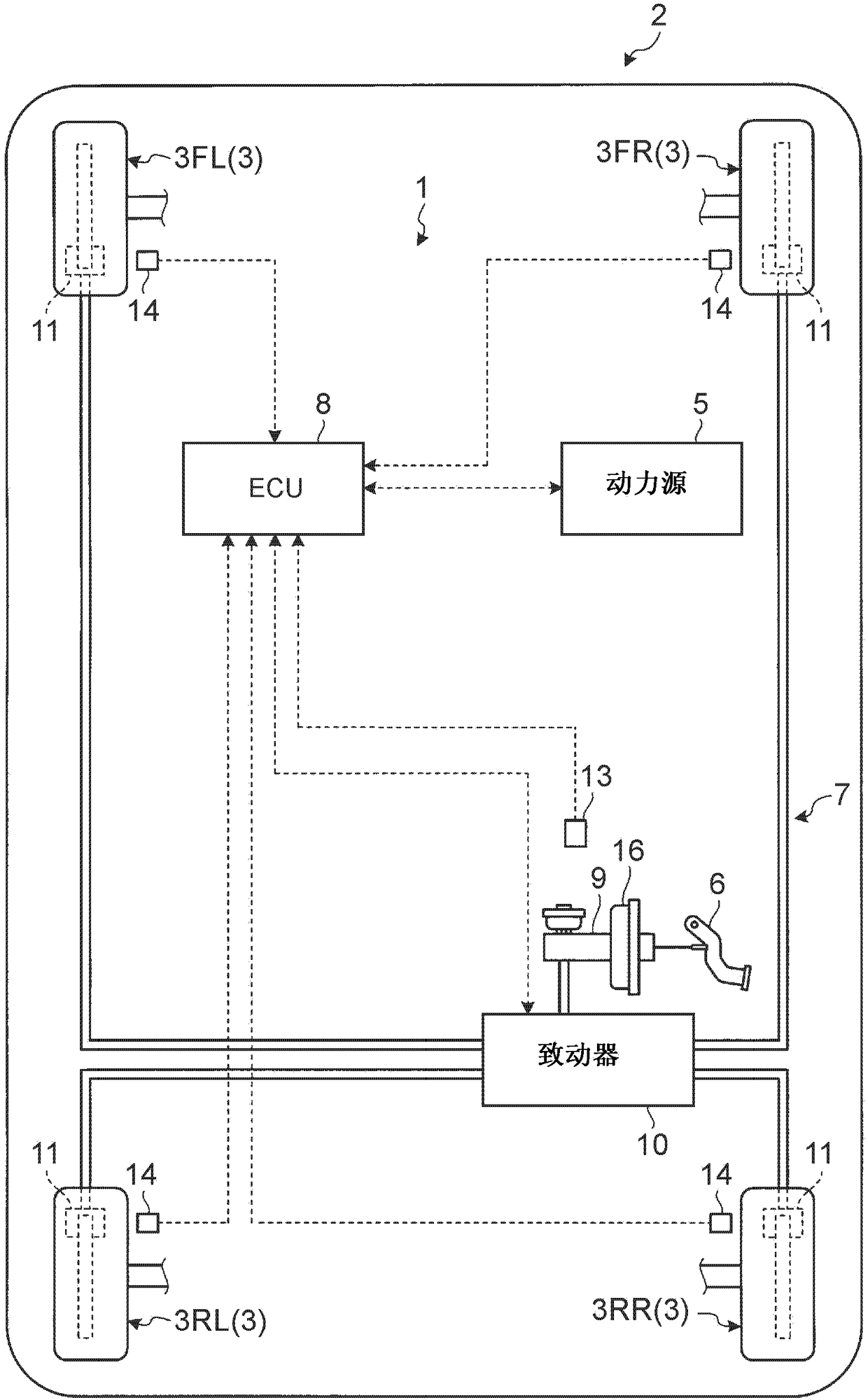
[0050] [Example] will refer to Figure 1 to Figure 24 Examples are described. This embodiment relates to a braking force control device. figure 1 is a diagram showing a schematic configuration of a vehicle according to an embodiment of the present invention.

[0051]The braking force control device 1 according to the present embodiment is mounted on a vehicle 2 and controls braking force generated in wheels 3 of the vehicle 2 . The vehicle 2 has a left front wheel 3FL, a right front wheel 3FR, a left rear wheel 3RL, and a right rear wheel 3RR. In this specification, the wheels 3FL, 3FR, 3RL, 3RR will simply be referred to as wheels 3 without specifically distinguishing the wheels 3FL, 3FR, 3RL, 3RR.

[0052] The vehicle 2 has wheels 3 and a power source 5 in addition to the braking force control device 1 . The braking force control device 1 according to the present embodiment includes an ECU 8 , a master cylinder pressure sensor 13 , and an actuator 10 of the braking devic...


PUM


Abstract

The present invention relates to a braking force control device (1), comprising: an actuator (10) for controlling the braking force generated in wheels (3FL, 3FR, 3RL, 3RR) of a vehicle (2); The command value is output to the control unit (8) of the actuator (10). The control unit is configured to perform at least one of processing of performing filtering on the required braking force based on the brake operation amount by using a filter having a damping ratio smaller than that of a pitching motion of the vehicle when the required braking force increases. processing to generate a braking force command value; and when the required braking force decreases, perform filtering processing on the required braking force based on the brake operation amount by using a filter having a damping ratio larger than that of the pitching motion of the vehicle, to generate Braking force command value.

Description

technical field [0001] The invention relates to a braking force control device. Background technique [0002] Brake control using filters is known in the prior art. As this type of brake control, Japanese Patent Application Laid-Open No. 2012-126352 discloses a technology on a vehicle braking device including: a brake operation amount detection device for outputting The operation amount of the brake is used as a detection signal; and a braking force generating device for generating a vehicle braking force according to the magnitude of the detection signal, the vehicle braking device includes: a pass filter; a second low pass filter having a second cutoff frequency lower than the first cutoff frequency in the detection signal; and a braking force target value setting means for selecting the output signal of the first lowpass filter and a stronger one of the output signals of the second low-pass filter to generate a braking force target value, and the braking force generatin...

Claims


Application Information

Patent Timeline
Patent Type & Authority Patents(China)
IPC IPC(8): B60T8/17
CPCB60T8/17B60T2270/82B60T8/171B60T2230/04
Inventor 门崎司朗加纳民夫森本知昭渡部大治
Owner TOYOTA JIDOSHA KK
Features
  • R&D
  • Intellectual Property
  • Life Sciences
  • Materials
  • Tech Scout
  • Unparalleled Data Quality
  • Higher Quality Content
  • 60% Fewer Hallucinations
Learn More