Supercharge Your Innovation With Domain-Expert AI Agents!

Drive circuit

A technology for driving circuits and driving signals, which is applied in the field of circuits, can solve problems such as the inability to further effectively improve the performance of output signals, and achieve the effect of improving performance

Active Publication Date: 2016-11-23
SEMICON MFG INT (SHANGHAI) CORP
View PDF4 Cites 0 Cited by
  • Summary
  • Abstract
  • Description
  • Claims
  • Application Information

AI Technical Summary

Problems solved by technology

[0008] The main purpose of the present invention is to provide a driving circuit to solve the problem that the performance of the output signal cannot be further effectively improved in the related art

Method used


Image

  • Drive circuit
  • Drive circuit
  • Drive circuit

Examples


Embodiment Construction

[0027] It should be noted that, in the case of no conflict, the embodiments in the present application and the features in the embodiments can be combined with each other. The present invention will be described in detail below with reference to the accompanying drawings and examples.

[0028] In order to enable those skilled in the art to better understand the solution of the present application, the technical solution in the embodiment of the application will be clearly and completely described below in conjunction with the accompanying drawings in the embodiment of the application. Obviously, the described embodiment is only It is an embodiment of a part of the application, but not all of the embodiments. Based on the embodiments in this application, all other embodiments obtained by persons of ordinary skill in the art without creative efforts shall fall within the scope of protection of this application.

[0029] It should be noted that the terms "first" and "second" in ...


PUM


Abstract

The invention discloses a drive circuit. The drive circuit comprises a logic gate circuit used for outputting a drive signal; a signal transmission circuit connected with an output end of the logic gate circuit and used for transmitting the drive signal; and a signal optimization part connected in parallel with the signal transmission circuit and used for optimizing the drive signal output by the logic gate circuit so as to obtain an optimized output signal. Through the drive circuit, the effect of improving the performance of the output signal of the logic gate circuit is achieved.

Description

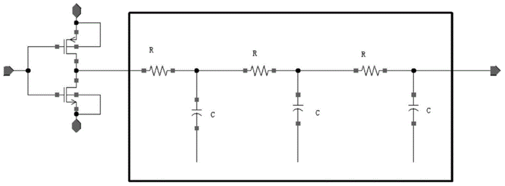
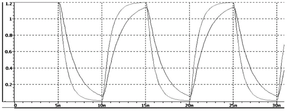
technical field [0001] The present invention relates to the field of circuits, in particular to a driving circuit. Background technique [0002] In integrated circuits with nanoscale technology, when long-line transmission (that is, transmission with a large load) is performed, the performance of the output signal of the inverter will often be deteriorated, especially in the transmission time of the output signal (Transition Time) and On the voltage amplitude, the transmission time (Transition Time) may be delayed, and the maximum and minimum values ​​of the voltage amplitude may be reduced. [0003] Such as figure 1 As shown, the line connected to the output end of the inverter for long-distance transmission can be equivalent to the π-RC circuit structure in the box in the figure. Among them, when the RC in the equivalent circuit is large, it can be found that there is a large deviation in the transmission time (Transition Time) and voltage amplitude of the output signal,...

Claims


Application Information

Patent Timeline
Patent Type & Authority Applications(China)
IPC IPC(8): H03K19/094
Inventor 方伟丁艳潘劲东
Owner SEMICON MFG INT (SHANGHAI) CORP
Features
  • R&D
  • Intellectual Property
  • Life Sciences
  • Materials
  • Tech Scout
  • Unparalleled Data Quality
  • Higher Quality Content
  • 60% Fewer Hallucinations
Learn More