Supercharge Your Innovation With Domain-Expert AI Agents!

A device for automatically taking out and disinfecting medical slippers

A disinfection device and slippers technology, applied in the direction of disinfection, water supply equipment, sanitary equipment for toilets, etc., can solve the problems of human body harm, high maintenance cost, and skin safety hazards, and achieve low maintenance cost, simple operation, and convenient use Effect

Active Publication Date: 2018-12-18
雷磊
View PDF2 Cites 0 Cited by
  • Summary
  • Abstract
  • Description
  • Claims
  • Application Information

AI Technical Summary

Problems solved by technology

[0002] With the development of society and the continuous improvement of medical standards, people have higher requirements for some medical equipment. The shoes usually worn in the operating room and working laboratory cannot enter, because there are many shoes that are usually worn. Bacteria will affect the air environment during surgery or in the working laboratory. Therefore, when entering such an environment, special medical slippers will be replaced. The daily maintenance of medical slippers must be disinfected to prevent bacteria from growing in the shoes. Existing Although the device has a strong disinfection effect, when taking out the shoes, they are all taken by hand. The ultraviolet germicidal lamp will cause certain harm to the human body, endanger the skin safety of the human body, and the maintenance cost is high. In order to meet market demand, better disinfection is required when disinfecting medical slippers. More complete equipment, so it is very necessary to design an automatic removal and disinfection device for medical slippers

Method used


Image

  • A device for automatically taking out and disinfecting medical slippers
  • A device for automatically taking out and disinfecting medical slippers
  • A device for automatically taking out and disinfecting medical slippers

Examples


Embodiment Construction

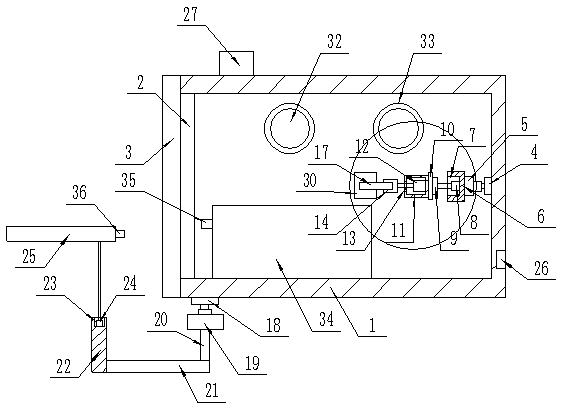
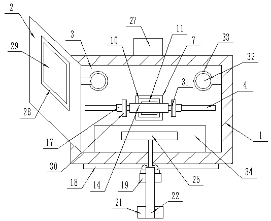
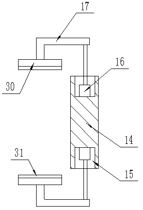
[0017] The present invention is specifically described below in conjunction with accompanying drawing, as Figure 1-4 As shown, a device for automatically taking out and disinfecting medical slippers includes a rectangular box (1), and a rectangular opening (2) is processed on the front surface of the rectangular box (1), and an electronic block is provided on the rectangular opening (2). The door (3), the inner and rear surface of the rectangular box (1) is provided with a slideway (4), the slideway (4) is provided with an electric trolley (5), and the front of the electric trolley (5) There is a mounting block (6) on the surface, and a circular groove (7) is processed at the center of the front surface of the mounting block (6). The circular groove (7) is provided with a rotating end for horizontal rotation The motor (8), the rotating end of the rotating motor (8) is provided with a top plate (9), the front surface of the top plate (9) is provided with a connecting plate (10...


PUM


Abstract

The invention discloses an automatic medical slipper taking-out sterilization device which comprises a rectangular box. A rectangular opening is formed in the front surface of the rectangular box, an electronic retaining door is arranged on the rectangular opening, a slide rail is arranged on the surface of the rear side in the rectangular box, an electric car is arranged on the slide rail, a mounting block is arranged on the front surface of the electric car, a commercial power interface is formed in the rear surface of the rectangular box, a controller is arranged on the upper surface of the rectangular box, a power terminal of the controller is connected with the commercial power interface through a wire, and an output end of the controller is respectively connected with the electronic retaining door, the electric car, a rotating motor, an electric pushing rod, a miniature linear motor, a second electric car and a second electric pushing rod through wires. The automatic medical slipper taking-out sterilization device has the advantages that bacteria can be more comprehensively treated in a rotating sterilization mode and cannot hide at any places, slippers are automatically clamped and taken out, and the device is convenient to use and prevents workers from indirectly contacting with an ultraviolet germicidal lamp.

Description

technical field [0001] The invention relates to the field of automatic removal and disinfection of medical slippers, in particular to an automatic removal and disinfection device for medical slippers. Background technique [0002] With the development of society and the continuous improvement of medical standards, people have higher requirements for some medical equipment. The shoes usually worn in the operating room and working laboratory cannot enter, because there are many shoes that are usually worn. Bacteria will affect the air environment during surgery or in the working laboratory. Therefore, when entering such an environment, special medical slippers will be replaced. The daily maintenance of medical slippers must be disinfected to prevent bacteria from growing in the shoes. Existing Although the device has a strong disinfection effect, when taking out the shoes, they are all taken by hand. The ultraviolet germicidal lamp will cause certain harm to the human body, en...

Claims


Application Information

Patent Timeline
Patent Type & Authority Patents(China)
IPC IPC(8): A61L2/10A61L2/24
CPCA61L2/10A61L2/24A61L2/26A61L2202/14
Inventor 王婷
Owner 雷磊
Features
  • R&D
  • Intellectual Property
  • Life Sciences
  • Materials
  • Tech Scout
  • Unparalleled Data Quality
  • Higher Quality Content
  • 60% Fewer Hallucinations
Learn More