
Soldering furnace with automatic slag removal function and working method thereof

An automatic slag removal and soldering furnace technology, which is applied in tin feeding devices, manufacturing tools, metal processing, etc., can solve problems such as the influence of welding fixed length devices, the inability to automatically remove tin slag, and the inability to automatically replenish tin liquid, etc., to achieve improved soldering performance. The effect of improving quality, preventing drastic temperature fluctuations, and improving efficiency

Active Publication Date: 2016-12-07
临沂亚欣电子科技有限公司
View PDF10 Cites 8 Cited by
  • Summary
  • Abstract
  • Description
  • Claims
  • Application Information

AI Technical Summary

Problems solved by technology

The scraper of the slag removal device of this rotary tin furnace is in a fixed state, which can only gather the tin slag together, and cannot automatically remove the accumulated tin slag. The tin slag needs to be removed manually, and at the same time, the tin liquid cannot be automatically replenished after the tin slag is removed. , which will affect the subsequent welding and fixing length device

Method used


Image

  • Soldering furnace with automatic slag removal function and working method thereof
  • Soldering furnace with automatic slag removal function and working method thereof
  • Soldering furnace with automatic slag removal function and working method thereof

Examples


Embodiment Construction

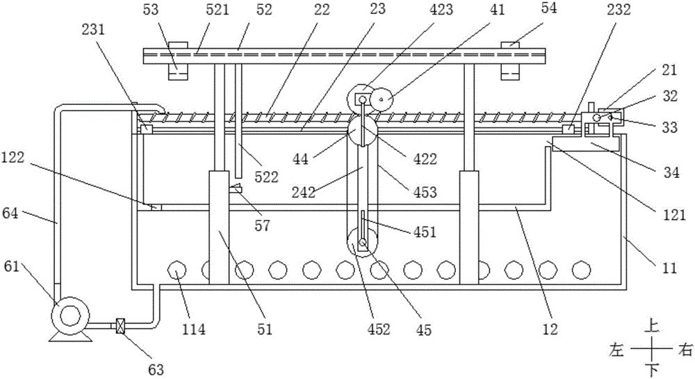
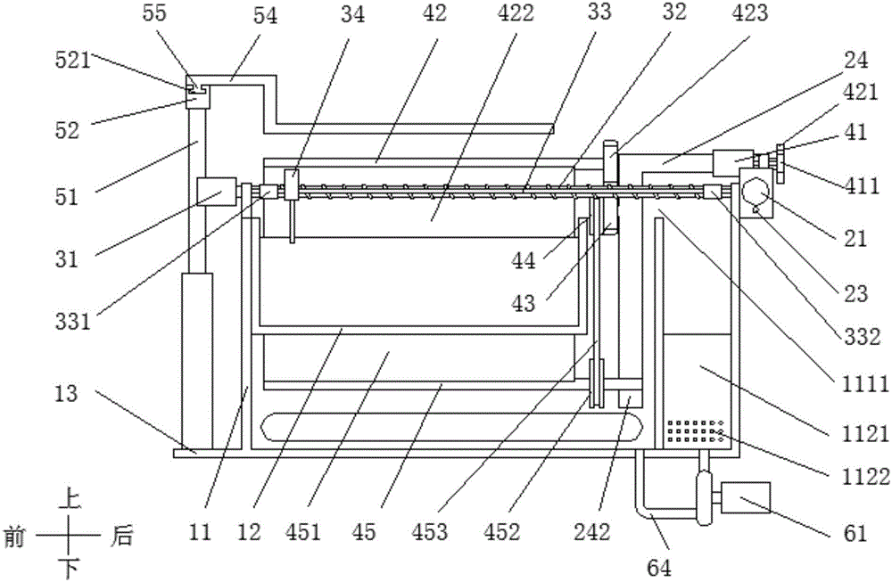
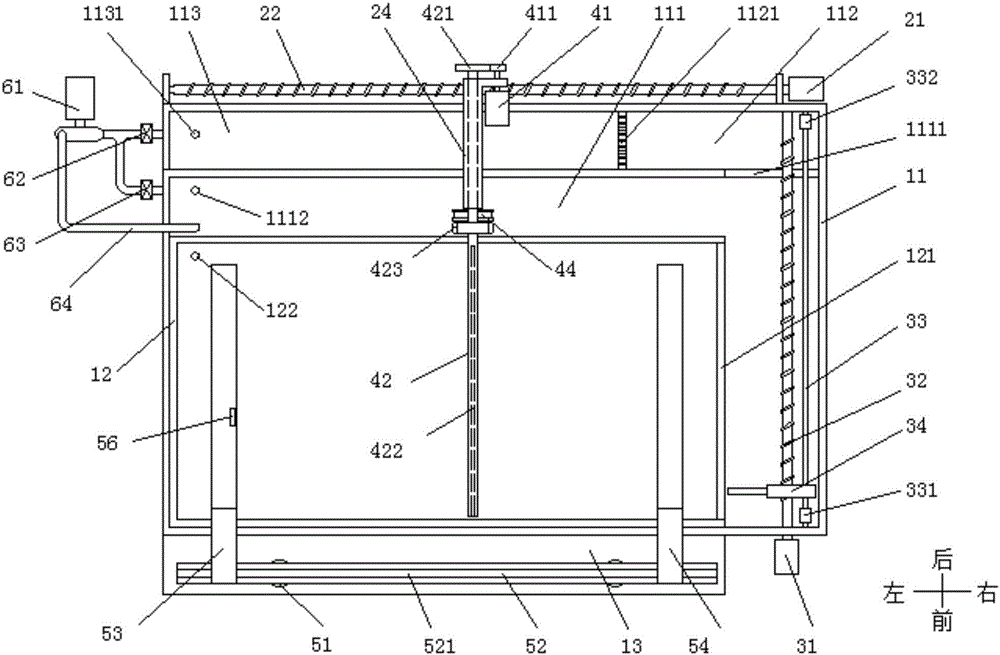
[0050] The present invention will now be described in further detail with reference to the drawings. These drawings are all simplified schematic diagrams, which merely illustrate the basic structure of the present invention in a schematic manner, so they only show the structures related to the present invention.

[0051] In addition, it should be noted that, unless otherwise specified or pointed out, the terms "first", "second", "front", "rear", "left", "right", and "up" may be involved in the specification. Descriptions such as "under" and "under" are only used to distinguish each component, element, step, etc. in the specification, rather than used to indicate the logical relationship or sequence relationship between each component, element, step, etc.

[0052] The related words of "forward work" and "reverse work" of the transverse motor 21, the longitudinal motor 31 and the slag removal motor 41 are only used for convenience of description, and do not represent the specific ope...


PUM


Abstract

The invention relates to a soldering furnace with an automatic slag removal function and a working method thereof. The soldering furnace comprises a tin melting assembly, slag removal assemblies, a feeding assembly and a circulating assembly. The tin melting assembly comprises a furnace body and an inner container, wherein the furnace body comprises a tin melting tank, a filtering tank and a tin collecting tank. An overflow opening is located between the tin melting tank and the filtering tank, a slag removal opening is formed in the side wall of the inner container, and a screening plate is arranged between the filtering tank and the tin collecting tank. The slag removal assemblies comprise the slag removal assembly for the inner container, the slag removal assembly for the tin melting tank and the slag removal assembly for the bottom of the inner container. The slag removal assemblies are driven by respective motors. Scrapers are used for scraping away tin slag. The feeding assembly comprises a guide rail which is jacked by lifting oil cylinders and provided with a left supporting arm and a right supporting arm, and an ejector rod can trigger a lifting limiting switch. The circulating assembly comprises a tin pump, a return valve and a tin discharging valve, wherein the return valve and the tin discharging valve are connected through a pipeline. The invention further discloses the working method of the soldering furnace. The stable temperature of tin liquor is guaranteed through the double-layer structure, tin slag can be automatically collected and removed, the liquor level of the tin liquor is automatically kept, and the tin liquor in the furnace body can be conveniently taken out.

Description

Technical field [0001] The invention belongs to the technical field of immersion tin, and in particular relates to a soldering furnace with automatic slag removal and a working method thereof. Background technique [0002] When wires and components are tinned, due to the reaction of flux, solder feet and hot tin, tin dross will be splashed and float on the surface of the tin liquid, which will cause poor quality of the next soldering material. The subsequent process It is easy to break the wire, making it impossible for the next step of production. At the same time, when the soldering furnace is working, the temperature of the tin liquid surface fluctuates widely, which will cause fatal damage to some components with high temperature requirements. [0003] The Chinese Patent Authorization Publication No. CN203080054U discloses a tin furnace with a tin slag filter. The tin furnace includes a furnace body. The furnace body is provided with a tin melting tank. The lower end of the tin...

Claims


Application Information

Patent Timeline
IPC IPC(8): B23K3/06B23K3/08B23K1/008B23K101/36
CPCB23K1/0016B23K1/008B23K3/0669B23K3/08
Inventor 赵珂
Owner 临沂亚欣电子科技有限公司
Learn More