Supercharge Your Innovation With Domain-Expert AI Agents!

A sample high-temperature shape tester and its imaging method

A tester and sample technology, applied in the field of detection and analysis, can solve problems such as low test efficiency and complex furnace tube design, and achieve the effects of improving sample test efficiency, improving energy utilization, and facilitating image acquisition

Active Publication Date: 2018-07-06
长沙开元仪器有限公司
View PDF7 Cites 0 Cited by
  • Summary
  • Abstract
  • Description
  • Claims
  • Application Information

AI Technical Summary

Problems solved by technology

[0005] The technical problem to be solved by the present invention is to solve the problem of low test efficiency and complex design of the furnace tube in the prior art

Method used


Image

  • A sample high-temperature shape tester and its imaging method
  • A sample high-temperature shape tester and its imaging method
  • A sample high-temperature shape tester and its imaging method

Examples


Embodiment 1

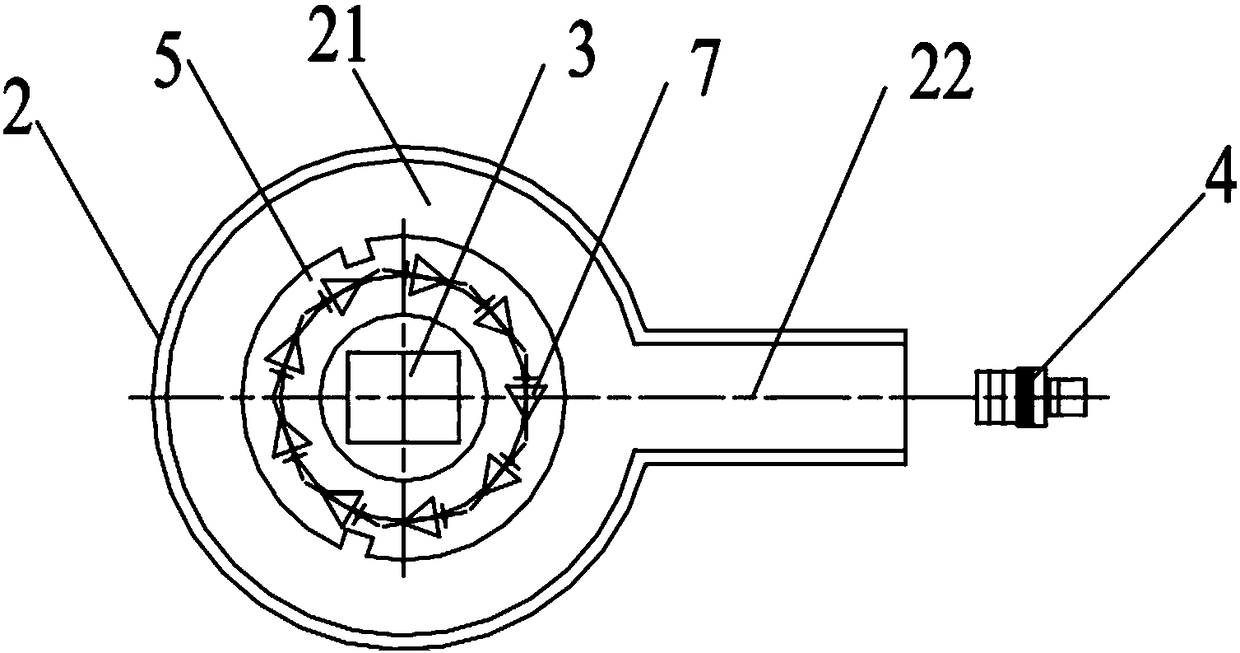
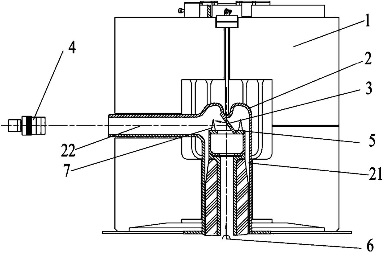
[0030] Such as Figure 2-Figure 4 As shown, a sample high-temperature form tester provided by the embodiment of the present invention can be used for the detection of the melting property of coal sample ash cones, the detection of the melting characteristics of biomass ash, the expansion coefficient, melting point, etc. of steel parts and the shape of samples at high temperatures. related testing. In this embodiment, the ash melting property used to measure coal sample ash cones is an example. The ash melting property tester includes a high-temperature furnace 1, a furnace tube 2, a background plate 3, an imaging assembly 4 and a disc-shaped supporting plate 5. The tube 2 is set in the high temperature furnace 1, the furnace tube 2 includes a sample placement cavity 21 and an imaging cavity 22 which is arranged on the side wall of the sample placement cavity 21 and communicates with the sample placement cavity 21, and the supporting plate 5 is arranged in the sample placement ...

Embodiment 2

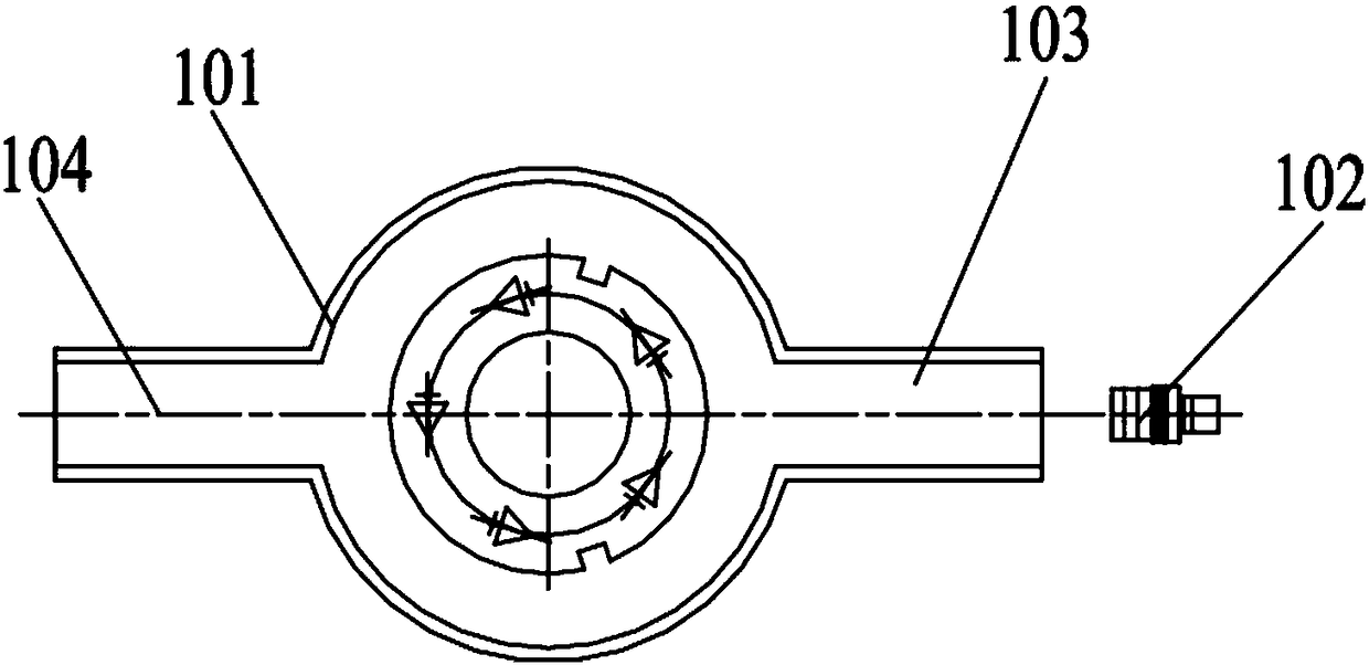
[0036] The technical content of the second embodiment that is the same as that of the first embodiment will not be described repeatedly, and the content disclosed in the first embodiment also belongs to the content disclosed in the second embodiment. The difference between the second embodiment and the first embodiment is that: Figure 5 and Figure 6 As shown, in this embodiment, the background plate 3 is a transmission element, the laser 6 is arranged outside the furnace tube 101 , and the emission end of the transmission element faces the ash cone 7 . When the light emitted by the laser 6 enters the background plate 3 , since the background plate 3 is a component with high transmittance, most of the energy can pass through the background plate 3 to form a bright background spot 61 on the background plate 3 .

Embodiment 3

[0038] The present embodiment 3 provides a kind of imaging method of above-mentioned ash fusion tester, comprises the following steps:

[0039] S1, when the gray cone 61 moves to the shooting range of the imaging assembly 4, the light spot 61 emitted by the laser 6 to the background plate 3 is displaced relative to the gray cone 7 until the movement track of the light spot 61 covers the entire gray cone 7 area; at the same time, the imaging component 4 performs continuous shooting.

[0040] Specifically, step S1 may be to move the spot 61 when the ash cone 7 is stationary: drive the ash awl 61 to rotate, and when the ash awl 61 moves into the shooting range of the imaging assembly 4, stop the movement of the ash awl 4 and drive the laser 6 The light spot 61 emitted to the background plate 3 moves, so that the movement track of the light spot 61 covers the area corresponding to the entire gray cone.

[0041] Step S1 can also be that the ash cone 7 moves when the light spot 61 ...


PUM


Abstract

The invention relates to the technical field of coal quality detection and analysis, in particular to a high-temperature shape tester for a sample and an imaging method for the sample. The high-temperature shape tester for the sample comprises a high-temperature furnace, a furnace tube, a background plate, an imaging assembly and a disk-shaped supporting plate, wherein the furnace tube is arranged in the high-temperature furnace, and the supporting plate is arranged in a sample placement cavity; the imaging assembly is used for acquiring an image of a to-be-detected sample on the supporting plate; the background plate is located at the middle part of the supporting plate and is opposite to the imaging cavity; the high-temperature shape tester further comprises a laser device, light spots projected by the laser device to the background plate form a bright background, the relative positions of the light spots and the to-be-detected sample are adjusted so as to enable the imaging assembly to shoot images of the to-be-detected sample at different light spot positions, and the images are synthesized by an image synthesis module to obtain a complete image of the to-be-detected sample. The light intensity of laser is concentrated, so that the high-temperature shape tester for the sample can ensure that the local strength is greater than the heat radiation strength in the furnace tube within the range where low power cannot be harmful to the safety of an operator; the high-temperature shape tester is particularly applicable to the test of the ash fusibility of an ash cone of a coal sample.

Description

technical field [0001] The invention relates to the technical field of detection and analysis, in particular to a sample high-temperature shape tester and an imaging method thereof. Background technique [0002] The ash melting test instrument is an instrument used to detect the melting of the ash cone of the coal sample. The melting of the ash cone is directly related to whether there is sintering in the boiler of the power plant and the severity of the sintering, and has a great impact on the safe use of boilers and cement shaft kilns. . In the current ash melting tester, the coal sample ash cone is arranged on the support plate, and the support plate is fixed on the support cup. During the test, the support cup drives the supporting plate to rotate, so that the coal sample ash cone rotates in the constant temperature zone of the high-temperature furnace tube and heats up evenly until the coal sample ash cone reaches a molten state. During this process, the camera mechan...

Claims


Application Information

Patent Timeline
Patent Type & Authority Patents(China)
IPC IPC(8): G01N25/02G01N21/84
CPCG01N21/84G01N25/02
Inventor 罗建文杨海涛罗彬彬杨辉洪廖炼斌
Owner 长沙开元仪器有限公司
Features
  • R&D
  • Intellectual Property
  • Life Sciences
  • Materials
  • Tech Scout
  • Unparalleled Data Quality
  • Higher Quality Content
  • 60% Fewer Hallucinations
Learn More