Supercharge Your Innovation With Domain-Expert AI Agents!

Apparatus and method for operating a light generator

A light generator and equipment technology, applied in the direction of light source, electric light source, electroluminescent light source, etc., to achieve the effect of simple cost, accurate and reliable work

Active Publication Date: 2016-12-14
IIE
View PDF5 Cites 0 Cited by
  • Summary
  • Abstract
  • Description
  • Claims
  • Application Information

AI Technical Summary

Problems solved by technology

So the said infrastructure is very problematic

Method used


Image

  • Apparatus and method for operating a light generator
  • Apparatus and method for operating a light generator

Examples


Embodiment Construction

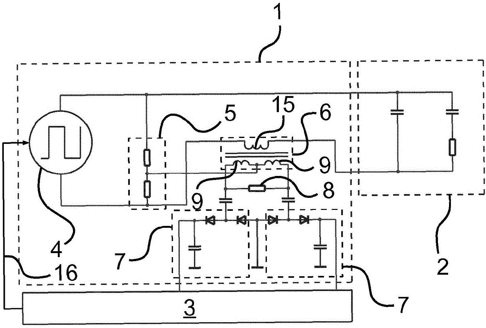
[0033] in accordance with figure 1 In the exemplary embodiment of the present invention, a voltage source 4 , a voltage divider 5 , a current measuring converter 6 and two rectifiers 7 are essentially arranged in the current feed device 1 . The current source 1 is connected to the lamp 2 and the control device 3 via electrical connections.

[0034] The voltage source 4 is designed as a rectangular generator and supplies a bipolar rectangular voltage. It is also possible to use single-stage rectangular voltages, or sinusoidal or sawtooth voltages (respectively single-stage or bipolar), however bipolar rectangular generators offer the best price / performance ratio. The voltage of the voltage source 4 is applied directly to the lamp 2 .

[0035] The voltage divider 5 serves to generate a measuring voltage proportional to the voltage applied to the lamp 2 . The voltage divider circuit ensures that the measurement voltage is changed corresponding to the voltage applied to the lam...


PUM


Abstract

The invention is based on an apparatus for operating a light generator (2) with a voltage source (4). The invention provides: a device (5; 13) for generating a measurement voltage proportional to the voltage present at the light generator (2), device (6, 9) for generating a first and a second comparison voltage, each proportional to the current flowing through the light generator (2), a device (9, 8) for forming a difference voltage from the measurement voltage and one comparison voltage and a summation voltage from the measurement voltage and the other comparison voltage, two capacitive rectifiers (7) for rectifying the difference voltage and the summation voltage, and a controller (3), by which the rectified difference voltage and the rectified summation voltage can be evaluated.

Description

technical field [0001] The invention relates to a device or a method for operating a light generator according to the preamble of claim 1 or the preamble of claim 7 . Background technique [0002] For rapid hardening of lacquers and pigments, UV generators are often used. UV generators are usually discharge lamps, which primarily emit light in the UV region. The UV generator operates in flash operation or continuously. [0003] The control and monitoring of such UV generators is very complex and problematic. In order to be able to ensure a continuous and trouble-free operation of the hardening plant, it must primarily be ascertained whether the UV generator has been switched on and whether it could go out during operation. In particular the UV power, which is largely dependent on the active power, is crucial if the power of the UV generator is also to be evaluated. However, depending on the lamp used, the ballast circuit and the frequency used, the real power may or may ...

Claims


Application Information

Patent Timeline
Patent Type & Authority Applications(China)
IPC IPC(8): H05B41/02H05B44/00
CPCH05B41/02H05B41/36
Inventor E·克雷斯
Owner IIE
Features
  • R&D
  • Intellectual Property
  • Life Sciences
  • Materials
  • Tech Scout
  • Unparalleled Data Quality
  • Higher Quality Content
  • 60% Fewer Hallucinations
Learn More