

Three-dimensional scanner based on galvanometer
A scanner and three-dimensional technology, applied in the field of three-dimensional measurement, can solve the problems of large size, high cost and high power consumption, and achieve the effect of small size, low cost and low power consumption
- Summary
- Abstract
- Description
- Claims
- Application Information
AI Technical Summary
Problems solved by technology
Method used
Image



Examples
Embodiment 1
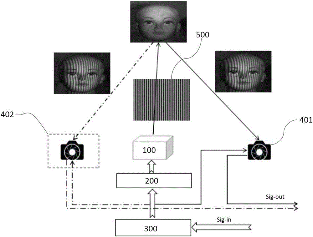
[0028] A galvo-based 3D scanner such as figure 1 As shown in the solid line, it includes a vibrating mirror 100, a vibrating mirror driving circuit 200, a system control circuit 300, and a first camera 401; the vibrating mirror 100 is connected to the vibrating mirror driving circuit 200, receives and responds to the vibrating mirror driving The vibrating mirror driving signal sent by the circuit 200; the vibrating mirror driving circuit 200 is connected to the system control circuit 300, receives and responds to the vibrating mirror control signal sent by the system control circuit 300; the first camera 401 and the described The system control circuit 300 is connected to receive and respond to the external trigger signal sent by the system control circuit 300; the system control circuit 300 receives the external control command Sig-in. The external control command Sig-in comes from a main control hardware system, and the main control hardware system includes a computer and an...
Embodiment 2
[0039] Such as figure 1 As shown by the solid line plus the dotted line, the difference between Embodiment 2 and Embodiment 1 is that a binocular three-dimensional scanner solution is provided, which also includes a second camera 402, and the second camera 402 and the first camera 401 are respectively connected with the system The control circuit 300 is connected. The system control circuit 300 receives the external control command Sig-in, and sends an external trigger signal to the first camera 401 and the second camera 402 at the same time, and the two cameras take pictures at the same time. The timing diagram is as follows image 3shown. After taking pictures, an image sequence Sig-out is output from the first camera 401 and the second camera 402 . For the solution of the multi-eye 3D scanner, refer to the solution of the binocular 3D scanner in Embodiment 2. It is only necessary to increase the number of cameras, and the multiple cameras are respectively connected to the...
Embodiment 3
[0041] The difference between Embodiment 3 and Embodiments 1 and 2 is that the vibrating mirror 100 is a one-dimensional scanning vibrating mirror, and the light energy distribution of the structured light field projected by the one-dimensional scanning vibrating mirror in the one-dimensional direction is determined by the vibrating mirror control signal Decide.
PUM
 Abstract
Description
Claims
Application Information