
High-definition network camera

A network camera and spherical camera technology, applied in the field of network equipment, can solve problems such as insufficient coverage, inflexible operation, and inability to focus on key monitoring, and achieve the effect of improving clarity, simple system, and comprehensive functions

Inactive Publication Date: 2017-01-04
HENAN MINGSHI SAFETY PRECAUTION ENG
View PDF6 Cites 3 Cited by
  • Summary
  • Abstract
  • Description
  • Claims
  • Application Information

AI Technical Summary

Problems solved by technology

Therefore, surveillance cameras have developed rapidly. At present, surveillance cameras of various structures have appeared, among which dome cameras are the most commonly used among many surveillance terminals. Development, high-definition network cameras also follow this trend, but the current network cameras are not flexible enough to focus on specific targets, and their coverage is not comprehensive enough. The image is transmitted to the monitor in the monitoring room, which does not meet the requirements of the mobile Internet era

Method used


Image

  • High-definition network camera
  • High-definition network camera

Examples


Embodiment 1

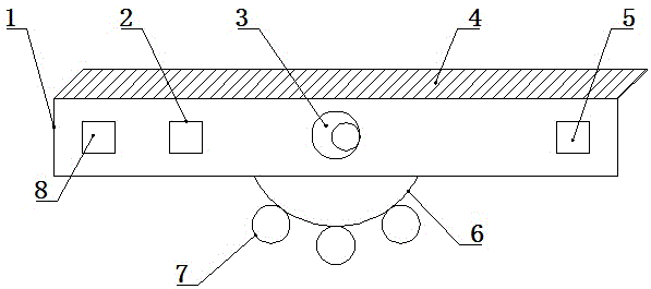
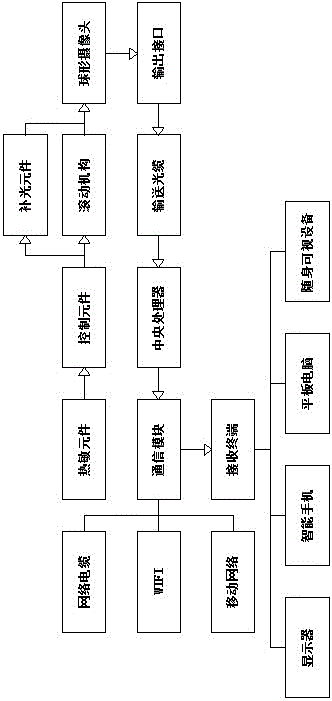
[0014] like figure 1 and figure 2 As shown, a high-definition network camera includes a connection base 1, the upper part of the connection base 1 is provided with an organic cover 4, and a heat-sensitive element 8, a control element 2 and an output interface 5 are arranged inside the connection base 1, A rolling mechanism 6 is arranged in the middle part of the lower side of the coupling seat 1, and a spherical camera 7 is uniformly arranged on the rolling mechanism 6, and a supplementary light element 3 is arranged in the middle part of the coupling seat 1. The input end of the control element 2 is connected with a thermal element 8, the output end of the control element 2 is connected with a supplementary light element 3 and a rolling mechanism 6, and the output end of the described light supplementary element 3 and the rolling mechanism 6 is connected with a spherical Camera 7, the output end of the spherical camera 7 is connected with an output interface 5, the output e...

Embodiment 2

[0017] like figure 1 and figure 2 As shown, a high-definition network camera includes a connection base 1, the upper part of the connection base 1 is provided with an organic cover 4, and a heat-sensitive element 8, a control element 2 and an output interface 5 are arranged inside the connection base 1, A rolling mechanism 6 is arranged in the middle part of the lower side of the coupling seat 1, and a spherical camera 7 is uniformly arranged on the rolling mechanism 6, and a supplementary light element 3 is arranged in the middle part of the coupling seat 1. The input end of the control element 2 is connected with a thermal element 8, the output end of the control element 2 is connected with a supplementary light element 3 and a rolling mechanism 6, and the output end of the described light supplementary element 3 and the rolling mechanism 6 is connected with a spherical Camera 7, the output end of the spherical camera 7 is connected with an output interface 5, the output e...


PUM


Abstract

The invention relates to a high-definition network camera. The high-definition network camera comprises a connecting seat, wherein a hood is arranged on the upper part of the connecting seat; a thermosensitive element, a control element and output interfaces are arranged in the connecting seat; a rolling mechanism is arranged in the middle of the lower side of the connecting seat; spherical camera heads are uniformly arranged on the rolling mechanism; a light supplementing element is arranged in the middle of the connecting seat; an input end of the control element is connected with the thermosensitive element; an output end of the control element is connected with the light supplementing element and the rolling mechanism; an output end of the light supplementing element and an output end of the rolling mechanism are connected with the spherical cameras; an output end of each spherical camera is connected with the corresponding output interface; an output end of each output interface is connected with a central processor through a conveying cable; an output end of the central processor is connected with a receiving terminal through a communication module; the communication module comprises a network cable, WIFI and a mobile network; and the receiving terminal comprises a display. In brief, the high-definition network camera has the advantages of wide coverage, high degree of automation, simple system and comprehensive functions.

Description

technical field [0001] The invention belongs to the technical field of network equipment, and in particular relates to a high-definition network camera. Background technique [0002] With the development of society, security issues are getting more and more attention from various fields. By arranging surveillance cameras to record the scene, it can restore the incident process very well and help to conduct follow-up investigations. Therefore, surveillance cameras have developed rapidly. At present, surveillance cameras of various structures have appeared, among which dome cameras are the most commonly used among many surveillance terminals. Development, high-definition network cameras also follow this trend, but the current network cameras are not flexible enough to focus on specific targets, and their coverage is not comprehensive enough. The images are transmitted to the monitors in the monitoring room, which does not meet the requirements of the mobile Internet era. Co...

Claims


Application Information

Patent Timeline
IPC IPC(8): H04N5/225H04N7/18
CPCH04N7/18H04N23/50H04N23/56
Inventor 桂洪洋赵强
Owner HENAN MINGSHI SAFETY PRECAUTION ENG
Features
  • Generate Ideas
  • Intellectual Property
  • Life Sciences
  • Materials
  • Tech Scout
  • Unparalleled Data Quality
  • Higher Quality Content
  • 60% Fewer Hallucinations
Learn More