Supercharge Your Innovation With Domain-Expert AI Agents!

A multi-scale photoacoustic microscopy imaging device and method thereof

An imaging device, photoacoustic microscopy technology, applied in measuring devices, acoustic wave diagnosis, infrasonic wave diagnosis, etc., can solve problems such as difficulty in obtaining rich depth information, inaccurate zoom precision, inconvenient operation, etc., and achieve corrected image resolution Seriously uneven rate, uniform image resolution and contrast, and improved detection sensitivity

Active Publication Date: 2019-05-07
广东光声医疗科技有限公司
View PDF7 Cites 0 Cited by
  • Summary
  • Abstract
  • Description
  • Claims
  • Application Information

AI Technical Summary

Problems solved by technology

[0003] The current photoacoustic microscopy imaging technology uses a single-focus ultrasonic probe for imaging. Since the focal length, focal depth and focal spot diameter of the single-focus ultrasonic probe are unique, this leads to It is difficult to obtain rich depth information, and it is difficult to achieve multi-level and multi-scale imaging effects in the depth direction; at the same time, the current photoacoustic microscopic imaging system generally uses a spherical focusing lens for optical focusing, but when the laser beam scans , a spherical focusing lens can only image on a circular plane, that is, the optical focus cannot be kept on the same plane, and there will be defocusing phenomenon; although there are some zoom-scanning photoacoustic microscopy imaging However, mechanical zoom is generally used, which is inconvenient to operate, and the precision of zoom is not accurate enough. It is difficult to accurately cooperate with multi-focus high-frequency detectors to achieve multi-focus photoacoustic confocal imaging, thus affecting the development of photoacoustic microscopy imaging technology. Practical application effect

Method used


Image

  • A multi-scale photoacoustic microscopy imaging device and method thereof
  • A multi-scale photoacoustic microscopy imaging device and method thereof
  • A multi-scale photoacoustic microscopy imaging device and method thereof

Examples


Embodiment Construction

[0042] The present invention will be further described in detail in conjunction with the accompanying drawings and specific embodiments.

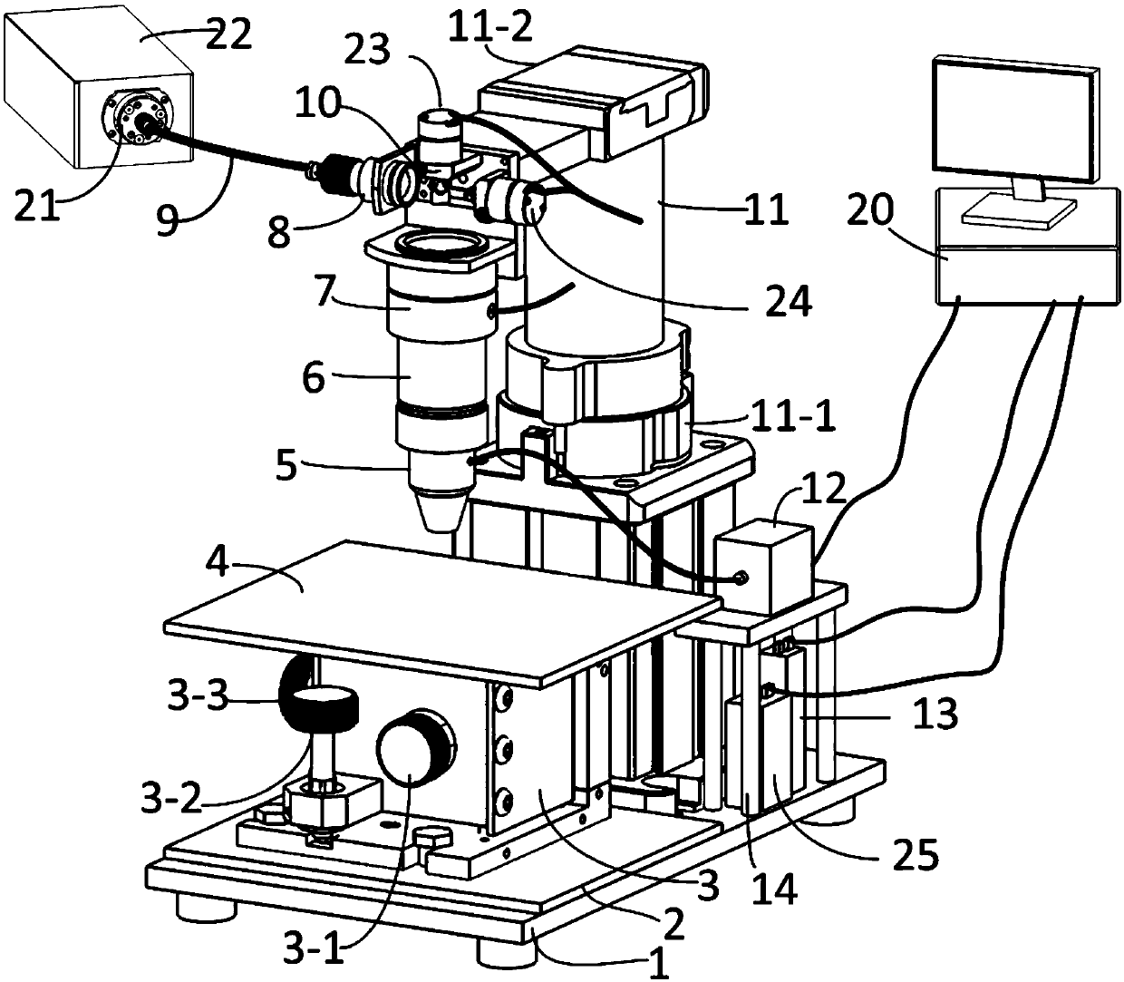
[0043] For the convenience of description, the up, down, left, right, front and back directions mentioned below are regulated as follows: the multi-focus high-frequency detector is located above the three-dimensional mobile platform, the electronic control adjustment platform is located behind the three-dimensional mobile platform, and the fixed platform is located on the right side of the electronic control adjustment platform; The up-down direction mentioned below is the vertical direction, the left-right direction mentioned below is the horizontal direction, and the front-back direction mentioned below is the longitudinal direction.

[0044] combine figure 1 As shown, a multi-scale photoacoustic microscopic imaging device includes a computer system, an electronic control adjustment platform, a three-dimensional mobile platform, a pulse l...


PUM

PropertyMeasurementUnit
electrical bandwidthaaaaaaaaaa
densityaaaaaaaaaa

Abstract

The invention relates to a multi-scale photo-acoustic micro-imaging device. An optical fiber coupler is arranged on a pulse laser; one end of a monomode optical fiber is connected to the optical fiber coupler, and the other end of the monomode optical fiber is connected with an optical fiber collimator; the optical fiber collimator, a two-dimensional scanning galvanometer and an optical electric-control focusing lens are arranged on an electrically controlled regulation platform; a flat field scanning lens is arranged at the lower end of the optical electric-control focusing lens; and a multi-focal high-frequency detector is arranged at the lower end of the flat field scanning lens. The multi-scale photo-acoustic micro-imaging device is capable of avoiding an optical focus shift phenomenon during photo-acoustic micro-imaging laser beam scanning, realizing multi-focal photo-acoustic confocal imaging at different depths on a same position, and acquiring high and even image resolution ratios and contrast ratios within a certain range. The invention further relates to a method for imaging by use of the multi-scale photo-acoustic micro-imaging device and belongs to the technical field of photo-acoustic micro-imaging.

Description

technical field [0001] The invention belongs to the technical field of photoacoustic microscopic imaging, and in particular relates to a multi-scale photoacoustic microscopic imaging device and a method thereof. Background technique [0002] Photoacoustic Microscopy (PAM) is a high-resolution nondestructive microscopic imaging method developed on the basis of PAI. By optically focusing the incident laser light, the focused point light source is used to excite tissues to generate high-frequency photoacoustics. The signal is imaged. It adopts optical focusing mode excitation, which has high contrast and high resolution; adopts high-frequency ultrasonic reception, and its imaging depth can reach 10mm while ensuring resolution. Commonly used traditional in vivo high-resolution optical imaging technologies - multiphoton microscopic imaging and optical coherence tomography (OCT) due to the scattering characteristics of light when propagating in biological tissues, its imaging dep...

Claims


Application Information

Patent Timeline
Patent Type & Authority Patents(China)
IPC IPC(8): A61B5/00A61B8/00G01N21/17
CPCA61B5/0095A61B8/00A61B8/4444A61B8/4455A61B2560/06G01N21/1702
Inventor 杨思华马海钢邢达
Owner 广东光声医疗科技有限公司
Features
  • R&D
  • Intellectual Property
  • Life Sciences
  • Materials
  • Tech Scout
  • Unparalleled Data Quality
  • Higher Quality Content
  • 60% Fewer Hallucinations
Learn More